Fume dehumidification process

A flue gas and process technology, which is applied in the field of flue gas treatment of coal-fired boilers, can solve the problems of high humidity emission and low temperature of flue gas, and achieve the effects of reducing equipment corrosion hazards, facilitating equipment installation, and reducing the accumulation of chloride ions

Active Publication Date: 2016-05-04
ANHUI UNIV OF SCI & TECH
View PDF4 Cites 5 Cited by
  • Summary
  • Abstract
  • Description
  • Claims
  • Application Information

AI Technical Summary

Problems solved by technology

[0006] This result directly leads to the emission of a larg

Method used


Image

  • Fume dehumidification process

Examples


Embodiment 1

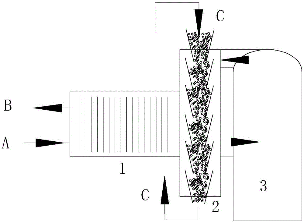
[0022] figure 1 Intermediate flue gas reheater 1, circulating dehumidifier 2, desulfurization island 3; high temperature flue gas A, reheated and purified flue gas B, desiccant C.

[0023] A circulating dehumidifier 2 is added between the desulfurization island 3 and the flue gas reheater 1. The circulating dehumidifier 2 is divided into upper and lower sections, the upper section is connected to the upper layer of the flue gas reheater 1, and the lower section is connected to the lower layer of the flue gas reheater 1; The desiccant C flows in multiple conical funnels connecting the upper and lower sections. In the upper section of the circulating dehumidifier 2, the desulfurized wet flue gas flows through the upper and lower cone annulus and contacts with the dry desiccant. The moisture in the flue gas is absorbed and dried. After being converted into a wet desiccant, it enters the lower section of the circulating dehumidifier 2; in the lower section of the circulating dehum...


PUM


Abstract

A fume dehumidification process is characterized in that a circulation dehumidifier is additionally arranged between a desulfurization island and a fume reheater; a drying agent flows in a plurality of conical funnels for enabling an upper section and a lower section of the circulation dehumidifier to communicate; at the upper section of the circulation dehumidifier, water in fume is absorbed, and a wet drying agent is dried by high-temperature fume to obtain a dry drying agent, and the dry drying agent is delivered to the upper section of the circulation dehumidifier by a lifting bucket to finish circulation of the drying agent, so that water in discharged desulfurized fume is reduced. The fume dehumidification process disclosed by the invention has the beneficial effects: (1) the fume is dehumidified and then heat is discharged, therefore haze is reduced; (2) the circulation of the drying agent is realized; (3) the circulation dehumidifier plays a role of bridging the desulfurization island with a fume reheater; (4) water consumption of a desulfurization system is reduced; (5) risk that the fume reheater equipment is blocked is eliminated; (6) quality of desulfurized gypsum is increased; (7) corrosion damage of the equipment is reduced; (8) heavy metal, such as mercury, can be removed.

Description

technical field [0001] The invention belongs to the field of flue gas treatment of coal-fired boilers. The invention relates to a flue gas dehumidification process, more specifically, a process method for reducing the moisture content of the flue gas discharged from a coal-fired boiler and combining with a flue gas reheater to raise the temperature of the flue gas and then discharge it. Background technique [0002] Entering the 21st century, my country's atmospheric governance has been increasing year by year. At present, almost 100% of thermal power plants are equipped with desulfurization equipment, and most of them are equipped with denitrification equipment. In recent years, thermal power plants have invested hundreds of billions in environmental protection. According to the detection data of emission indicators provided by the environmental protection department, the smog is still getting worse. [0003] A very important reason for this phenomenon is that my country's...

Claims


Application Information

Patent Timeline
IPC IPC(8): B01D53/26
CPCB01D53/263B01D2257/80B01D2258/0283
Inventor 陶俊周俊生邓军王蓓蓓张倩倩刘肖叶良田冬冬李恕洲
Owner ANHUI UNIV OF SCI & TECH
Why Eureka
Try Eureka