
Filter with circulation filtering layer

A filter and filter layer technology, applied in the direction of filtration separation, mobile filter element filter, separation method, etc., can solve the problems of not being too strong, poor cleaning effect, low dirt interception ability and filtration precision, etc., and reach the service life Long, easy to replace, improve the effect of interception capacity

Inactive Publication Date: 2016-05-04
曲晓东
View PDF5 Cites 2 Cited by
  • Summary
  • Abstract
  • Description
  • Claims
  • Application Information

AI Technical Summary

Problems solved by technology

The existing filtering equipment mainly has the following problems: 1. The strength of the filter layer formed by stacking loose filter materials should not be too large during cleaning, otherwise chaotic layers and material running will occur, so the cleaning effect is poor; 2. The filter layer can reach Saturation requires cleaning and regeneration, and the equipment cannot work continuously; 3. The thickness of the filter layer determines the interception capacity and filtration accuracy. The thicker the filter layer, the greater the head loss, the higher the height of the equipment, and the thinner the filter layer, the greater the interception capacity and filtration accuracy. The lower the filtration accuracy; 4. When the turbidity of raw water exceeds 50NTU, the filter layer will fail in a short time; 5. The filtered water must be water after coagulation and sedimentation treatment; 6. It cannot be used for water containing Filtration of sewage such as sludge, algae, sand and gravel

Method used


Image

  • Filter with circulation filtering layer
  • Filter with circulation filtering layer
  • Filter with circulation filtering layer

Examples


Embodiment Construction

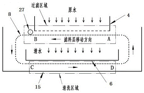
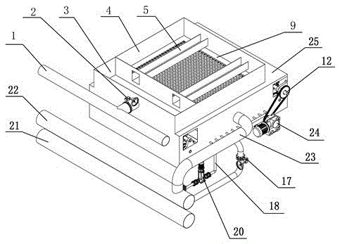
[0018] refer to Figure 1-Figure 5 , the circulating filter layer filter of the present invention comprises a housing 25, a water distribution tank 4 is provided on the top of the housing 25, a front water tank 3 is provided at the front of the water distribution tank 4, and a front water tank 3 is provided in the distribution tank 4. The connected water guide tank 5, the front water tank 3 is connected with the raw water pipe 1 through the water inlet valve 2, the bottom of the water distribution pool 4 has a water distribution orifice plate 9, and the water holes are uniformly arranged on the water distribution orifice plate 9, and the opening ratio is determined according to the amount of treated water. Calculate to ensure the uniformity of water distribution. The upper end of the sealing cover 7 is fixed on the lower end surface of the water distribution orifice 9, and the lower end of the sealing cover 7 is in contact with the upper layer of the circulating filter layer 8...


PUM


Abstract

A filter with a circulation filtering layer is characterized in that a water distributing pond arranged at the upper portion of a shell is connected with a raw water pipe, a water distributing hole plate at the bottom of the water distributing pond and the upper end of a sealing cover are fixed, and the lower end of the sealing cover is in contact with the upper layer of the circulation filtering layer; a driving shaft and three driven shafts are arranged in a rectangle mode on the two side walls of the shell, the driving shaft is fixedly connected with a power device, the two ends of the driving shaft are fixedly connected with a driving chain wheel, and the two ends of each driven shaft are fixedly connected with a driven chain wheel; a supporting chain fixed by the circulation filtering layer is connected to the driving chain wheel and the driven chain wheel in a wrapped mode, the upper layer of the circulation filtering layer strides a clear water collecting pond, and the lower layer of the circulation filtering layer is arranged in a washing pond; the circulation filtering layer surrounds the clear water collecting pond, and the clear water collecting pond is connected with a clear water outlet pipe through water draining holes in the side walls; a plurality of washing sprayers arranged on the lower part of the clear water collecting pond are connected with a washing pump and a clear water header pipe through a washing pipeline. The filter has the advantages of being high in intercepting capability, high in filtering precision, good in outlet water quality and wide in application range.

Description

technical field [0001] The invention belongs to water treatment filtering equipment, and is a circulating filter layer filter, which is suitable for filtering various suspended solids, colloids and other particulate matter in water. Background technique [0002] The filter material layer of existing water treatment filter equipment is all stacked or fixed in the pond body of filter tank, as quartz sand, fiber ball, comet filter material, fiber bundle and filter cloth etc. The process is: filter → filter layer cleaning → filter circulation process. The existing filtering equipment mainly has the following problems: 1. The strength of the filter layer formed by stacking loose filter materials should not be too large during cleaning, otherwise chaotic layers and material running will occur, so the cleaning effect is poor; 2. The filter layer can reach Saturation requires cleaning and regeneration, and the equipment cannot work continuously; 3. The thickness of the filter layer...

Claims


Application Information

Patent Timeline
Patent Type & Authority Applications(China)
IPC IPC(8): B01D33/04B01D33/48B01D33/72
CPCB01D33/04B01D33/042B01D33/48B01D33/705B01D33/72
Inventor 曲晓东
Owner 曲晓东
Learn More