Adjustable vane apparatus and sectional type multiple-stage centrifugal pump

A technology of a guide vane device and a centrifugal pump, which is applied to non-variable volume pumps, non-displacement pumps, and components of pumping devices for elastic fluids, etc., can solve problems such as low efficiency and decreased efficiency, and improve hydraulic power. The effect of efficiency, energy saving and easy maintenance

Active Publication Date: 2016-04-27
上海上涵自动化科技有限公司
View PDF7 Cites 1 Cited by
  • Summary
  • Abstract
  • Description
  • Claims
  • Application Information

AI Technical Summary

Problems solved by technology

In the field of water pump systems, the commonly used method is to use frequency conversion technology. Frequency conversion technology has made a great contribution to the energy saving of water pump systems. However, the design of water pumps is optimized according to the rated point (that is, the efficiency of the water pump is the highest at the rated flow rate). When the pump deviates from the rated point, that is, under partial load and overload conditions, its efficiency is low, and the farther it deviates from the rated flow, the more its efficiency drops
[0005] The purpose of the present invention is to propose an adjustable guide vane device and a new type of section-type centrifugal pump using the adjustable guide vane device for the technical defects of low efficiency under partial load and overload conditions of the existing segmental multistage centrifugal pump. Segment multistage centrifugal pump

Method used


Image

  • Adjustable vane apparatus and sectional type multiple-stage centrifugal pump
  • Adjustable vane apparatus and sectional type multiple-stage centrifugal pump
  • Adjustable vane apparatus and sectional type multiple-stage centrifugal pump

Examples


Embodiment Construction

[0051] The following will clearly and completely describe the technical solutions in the embodiments of the present invention with reference to the drawings in the embodiments of the present invention.

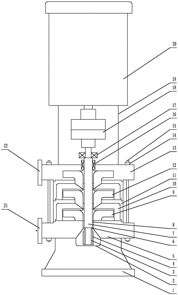
[0052] Such as figure 1 As shown, the segmental multistage centrifugal pump of the present invention specifically includes: base 1, bearing housing 2, bushing 3, sliding bearing 4, water inlet section 5, retaining ring 6, pump shaft 7, impeller spacer ring 8, first Stage impeller 9, adjustable guide vane device 10, middle section 11, secondary impeller 12, water outlet section 13, mechanical seal 16, rolling bearing 17, coupling 18, motor bracket 19 and motor 20, wherein the water outlet section 13 passes bolts 15 nuts 14 is connected with the motor bracket 19, and the water outlet section 13 and the pump shaft 7 are sealed by a mechanical seal 16; the flow channel of the liquid in the water inlet section 5 is the flow channel, and the mouth of the flow channel is the suction ...


PUM


Abstract

The invention discloses a sectional type multiple-stage centrifugal pump provided with an adjustable vane apparatus. The sectional type multiple-stage centrifugal pump comprises a suction section, a first-stage impeller, the adjustable vane apparatus, a middle section, a second-stage impeller, a discharging section, a pump shaft, a shaft sleeve, an impeller spacer ring, a sliding bearing, a rolling bearing, an elastic connector and an external prime motor; the impellers are assembled on the pump shaft in a key connection manner; and the adjustable vane apparatus is assembled in the middle section, liquid pressurized by the impellers is collected through the adjustable vane apparatus, the flow speed of the liquid is decreased, and the liquid is discharged and fed into a pipe system. By means of the adjustable vane apparatus, the angle of guide vanes is adjusted according to the pressure at an outlet of the water pump, so that the water pump works at efficiency optimizing working points at any working conditions, partial loads of the water pump and the hydraulic efficiency under the overload working condition are improved, the running efficiency of a water pump system, in particular to a frequency conversion or flow changing water pump system is improved, and energy consumption of the water pump system is saved.

Description

technical field [0001] The invention relates to the fields of liquid transportation such as industry and agriculture, in particular to an adjustable guide vane device and a vertically installed segmental multistage centrifugal pump using the device. Background technique [0002] Segmental multistage centrifugal pump is to install multiple impellers on a shaft to work in series, and the number of impellers on the shaft represents the number of stages of the pump. The segmental multistage pump structure is generally divided into a water inlet section, a middle section (the number of the middle section is the number of impellers minus 1) and a water outlet section, and each section is connected into a whole with tension bolts. The suction inlets of the segmental multistage centrifugal pumps are arranged in the same direction. The liquid flows out from the previous stage impeller and enters the inlet of the next stage impeller through the guide vane, so that the energy increas...

Claims


Application Information

Patent Timeline
IPC IPC(8): F04D29/46F04D1/06
CPCF04D1/06F04D29/466
Inventor 任向前陈拥军
Owner 上海上涵自动化科技有限公司
Why Eureka
Try Eureka