
Two-dimensional oscillation of a continuous casting mould

A technology of mold and continuous casting machine, applied in the field of mold (also known as continuous casting mold) oscillation, can solve the problems of high complexity and difficult to use, and achieve the effect of effective lubrication and improved lubrication

Active Publication Date: 2016-04-20
PRIMETALS TECH AUSTRIA GMBH
View PDF6 Cites 2 Cited by
  • Summary
  • Abstract
  • Description
  • Claims
  • Application Information

AI Technical Summary

Problems solved by technology

Due to the high complexity, the method or the device is practically difficult to use

Method used


Image

  • Two-dimensional oscillation of a continuous casting mould
  • Two-dimensional oscillation of a continuous casting mould
  • Two-dimensional oscillation of a continuous casting mould

Examples


Embodiment Construction

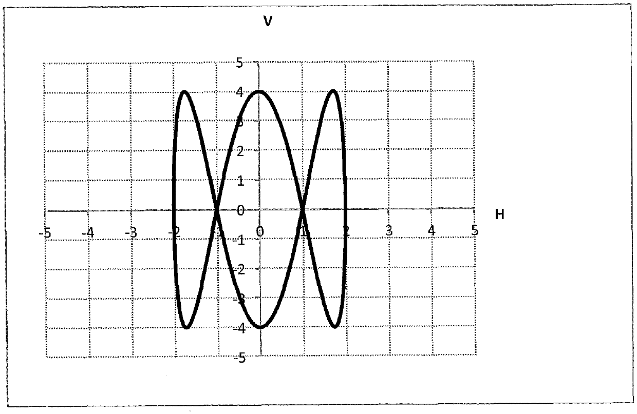
[0042] exist figure 1 shows the trajectory curve (also referred to as motion trajectory) with respect to the broad side of a vertically oscillating mold according to the prior art during one-dimensional oscillation. It can be seen directly from the trajectory curve that the direction of movement of the mold—and thus also of the broad side plates—reverses correspondingly in the top dead center OT and in the bottom dead center; moreover, v≡0 holds true for the velocity v of the mold in the two dead centers OT and UT. Furthermore, the acceleration of the mold in the dead points OT and UT has exactly a maximum value (if for example s=A.sin(ω.t) holds for a displacement s along the vertical y direction), then For the velocity v and the acceleration a, apply v= =A.ω.cos(ω.t) and a= =-A.ω 2 .sin(ω.t). By having │a│=A.ω in the dead points OT and UT 2 Due to the higher acceleration a and the higher friction associated therewith: the strand shell or the casting powder which is s...


PUM


Abstract

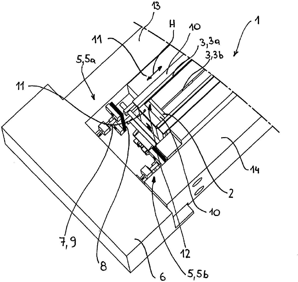
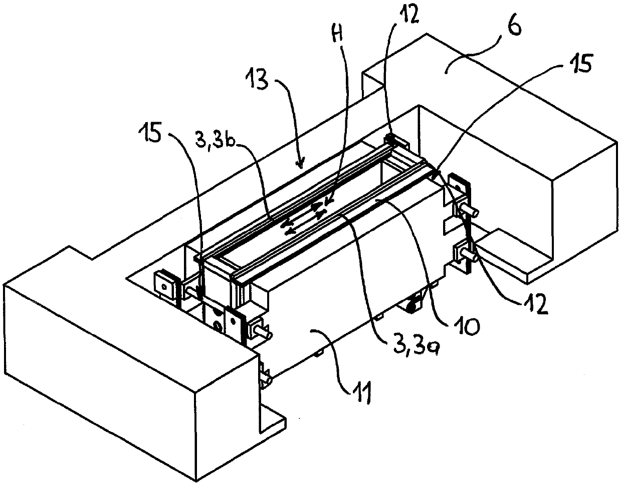
The invention relates to a method and a device for oscillating a mould (1) of a continuous casting machine. The object of the invention is to provide a method for oscillating a mould (1) of a continuous casting machine, wherein the strand is better lubricated by the casting powder, and the strand has fewer oscillation marks. To achieve this object, at least one long-side plate (3, 3a, 3b) of the mould (1) oscillates horizontally in the direction of the length (H) of the long-side plate (3, 3a, 3b) with f[H] , where f[v] is not equal to f[H] , and for all points of the locus curve of the long-side plate (3) the magnitude of the velocity in numerical formula (I) is greater than 0.

Description

technical field [0001] The invention relates to a method and a device for oscillating a mold of a continuous casting machine, also known as a continuous casting mold. [0002] In one aspect, the invention relates to a method for oscillating a mold (Kokille) of a continuous casting machine, wherein said mold comprises two narrow side plates and two wide side plates, and said mold follows a vertical orientation relative to a position-fixed support structure at a first frequency f v Shake. [0003] In another aspect, the invention relates to a device for oscillating a mold of a continuous casting machine, the device having: [0004] - a crystallizer provided with a substantially rectangular shaped cavity, wherein said crystallizer comprises two narrow side plates and two wide side plates; and [0005] - A first oscillating mechanism for oscillating said crystallizer in a vertical direction relative to a stationary support structure. Background technique [0006] It has long...

Claims


Application Information

Patent Timeline
Patent Type & Authority Applications(China)
IPC IPC(8): B22D11/053B22D11/16
CPCB22D11/051B22D11/053B22D11/166B22D11/0535
Inventor G.莱特纳M.穆伊巴奇勒J.瓦特辛格
Owner PRIMETALS TECH AUSTRIA GMBH
Learn More