
Switching method and system based on carrier aggregation

A carrier aggregation and switching system technology, applied in wireless communication, electrical components and other directions, can solve the problems of increasing the switching operation time, affecting the switching success rate, inter-carrier signal interference, etc., so as to reduce the inter-carrier signal interference and ensure the service quality of services. , the effect of reducing the switching delay

Active Publication Date: 2016-04-20
COMBA TELECOM SYST CHINA LTD
View PDF5 Cites 13 Cited by
  • Summary
  • Abstract
  • Description
  • Claims
  • Application Information

AI Technical Summary

Problems solved by technology

However, in the carrier aggregation scenario, due to the multi-carrier selection and activation operations, and the radio resource management between multi-carriers, the handover operation time is increased; specifically, due to the delay in the carrier aggregation process during handover, or the determination The problem of high time consumption in the process of target base station cell list
There are also problems such as signal interference between multiple carriers that affect the success rate of handover, such as: signal interference caused by mutual data transmission between multiple carriers, or the rationality of the cell list determined by the target base station, resulting in handover failure
[0004] It can be seen that the handover time of the traditional handover method based on carrier aggregation is prolonged, and there is signal interference between carriers, which makes it difficult to guarantee the service quality of the user equipment during the mobile process

Method used


Image

  • Switching method and system based on carrier aggregation
  • Switching method and system based on carrier aggregation
  • Switching method and system based on carrier aggregation

Examples


Embodiment Construction

[0030] In order to make the purpose, features and advantages of the present invention more obvious and understandable, the technical solutions in the embodiments of the present invention will be clearly and completely described below in conjunction with the accompanying drawings in the embodiments of the present invention. Obviously, the described The embodiments are only some of the embodiments of the present invention, but not all of them. Based on the embodiments of the present invention, all other embodiments obtained by persons of ordinary skill in the art without making creative efforts belong to the protection scope of the present invention.

[0031] The embodiments provided by the present invention include embodiments of the handover method based on carrier aggregation, and also include corresponding embodiments of the handover system based on carrier aggregation. Each will be described in detail below.

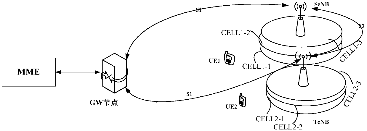
[0032] figure 1 It is a schematic diagram of a hardware enviro...


PUM


Abstract

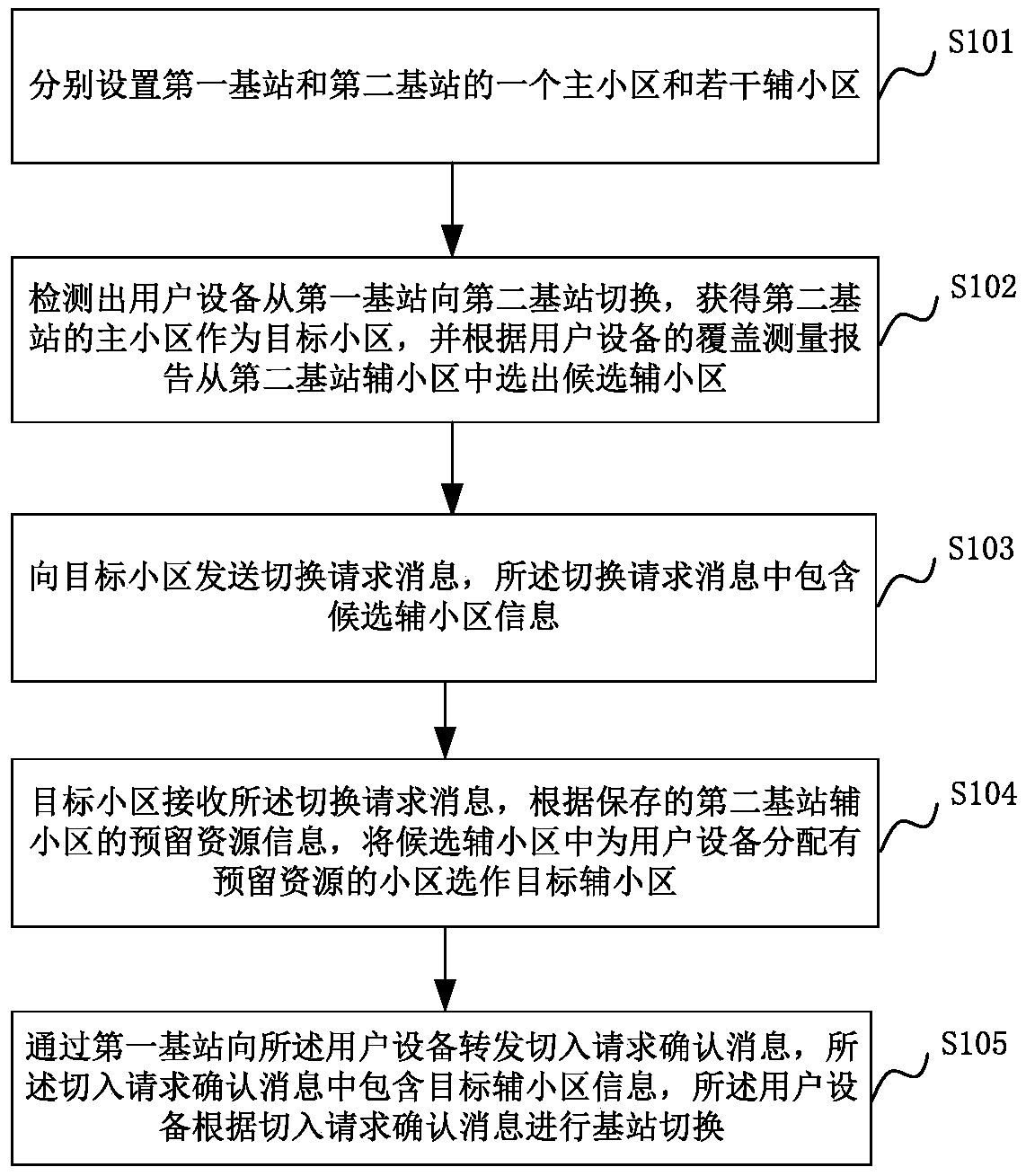
The invention relates to a switching method and system based on carrier aggregation. The method comprises: respectively setting a main cell and a plurality of auxiliary cells of a first base station and a second base station; the main cells are used for scheduling information transmission; the auxiliary cells are used for data information transmission of the user equipment in the main cells of the base stations; detecting that the user equipment is switched from the first base station to the second base station, obtaining the main cell in the second base station as a target cell, selecting candidate auxiliary cells from the auxiliary cells of the second base station according to the coverage measurement report of the user equipment; sending a switching request message to the target cell, wherein the switching request message contains candidate auxiliary cell information; selecting a target auxiliary cell from the candidate auxiliary cells by the target cell according to the stored reservation resource information of the auxiliary cells of the second base station; and forwarding a switching request confirmation message containing target auxiliary cell information to the user equipment. According to the invention, the switching time delay is reduced and the signal interference among the carriers is reduced.

Description

technical field [0001] The present invention relates to the technical field of wireless communication, in particular to a switching method and system based on carrier aggregation. Background technique [0002] With the development of Long Term Evolution (hereinafter referred to as LTE) technology for mobile communications, the traffic volume and data throughput of LTE users continue to increase, and traditional LTE can no longer meet user needs, so LTE-Advanced technology evolved, which introduced a landmark Technology: carrier aggregation technology. Carrier aggregation technology can aggregate multiple carriers into a wider spectrum, and at the same time, aggregate some discontinuous spectrum fragments together to form a wider spectrum, aiming to provide users with higher rates. With the development of 4G services and the continuous advancement of speed competition, operators' demand for spectrum resources is increasing day by day. Since the total spectrum resources are ...

Claims


Application Information

Patent Timeline
Patent Type & Authority Applications(China)
IPC IPC(8): H04W36/00H04W36/08
CPCH04W36/0083H04W36/08
Inventor 冯芳王超夏裕坚习益锋李树春
Owner COMBA TELECOM SYST CHINA LTD
Learn More