
Buck-boost isolation type DC/DC circuit-based DC power spring topology and control method thereof

A power spring, buck-boost technology, applied in the field of smart grid operation control, can solve problems such as the inability to meet the large-scale, high-proportion distributed generation grid connection of smart grid, expensive construction cost and reliability, and achieve capacity charge and discharge capacity. Requirement reduction, maintenance voltage, cost reduction effect

Active Publication Date: 2016-04-20
SOUTHEAST UNIV
View PDF4 Cites 17 Cited by
  • Summary
  • Abstract
  • Description
  • Claims
  • Application Information

AI Technical Summary

Problems solved by technology

However, similar to the dilemma faced by the current AC power supply system, the expensive cost of energy storage equipment such as large-capacity batteries and flywheel energy storage devices and the centralized control method with low reliability cannot meet the needs of large-scale and high-proportion in the future smart grid. Requirements for grid-connected distributed generation
Alternative Current Electric Spring (ACES), which came out in recent years, has solved this problem to a certain extent and is considered to be widely used in distributed power generation systems. However, the advent of ACES is mainly for AC microgrid applications. There are no relevant reports on the application of DC electric springs (Direct Current Electric Spring, DCES) based on the principle of smart loads to DC microgrids.

Method used


Image

  • Buck-boost isolation type DC/DC circuit-based DC power spring topology and control method thereof
  • Buck-boost isolation type DC/DC circuit-based DC power spring topology and control method thereof
  • Buck-boost isolation type DC/DC circuit-based DC power spring topology and control method thereof

Examples


Embodiment Construction

[0027] The present invention will be further explained below in conjunction with the accompanying drawings.

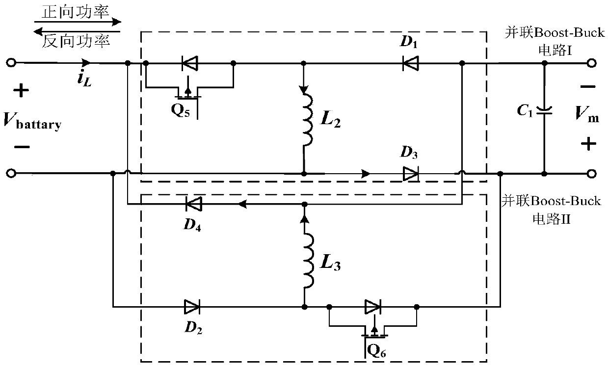
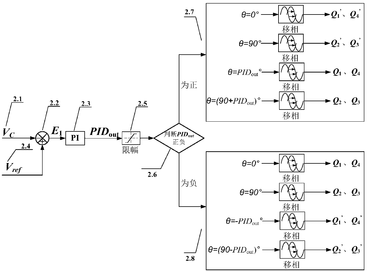
[0028] Such as figure 1 As shown, a DC power spring topology based on buck-boost and isolated DC / DC circuits, including isolated full-bridge bidirectional DC / DC converter, bidirectional buck-boost DC / DC converter, H-bridge and energy storage device. The input terminals of the bidirectional buck-boost DC / DC converter and the isolated full-bridge DC / DC converter are connected in parallel at both ends of the energy storage device, and the key load R c It is connected in parallel at the output end of the full-bridge bidirectional DC / DC converter, and a filter capacitor C is connected in parallel at both ends of the key load. 3 . The output terminal of the bidirectional buck-boost DC / DC converter is cascaded with the H-bridge, and the cascaded output voltage is connected to the non-critical load R nc Connect in parallel with critical loads after series connection. New ...


PUM


Abstract

The invention discloses a buck-boost isolation type DC / DC circuit-based DC power spring topology and a control method thereof. Based on the definition of a current electric spring (ES) on a critical load and a non-critical load, when the generated power output DC voltage of a renewable energy source deviates from a normal value, a direct current electric spring (DCES) realizes the dynamic balance between the power supply and the load energy through dynamically adjusting the equivalent resistance value of the non-critical load. Furthermore, the terminal voltage of the critical load is stabilized. The above DC power spring topology and the control method thereof are high in practical value and easy in popularization, thus being especially applicable to roof photovoltaic power generation systems and small-scale wind power generation systems in ordinary families and residential communities. Meanwhile, the non-critical load bears a considerable part of the power fluctuation. Therefore, the requirement on the charge and discharge capacity of a storage battery pack is significantly reduced, and the cost of energy storage equipment is lowered.

Description

technical field [0001] The invention relates to the technical field of smart grid operation control, in particular to a DC power spring topology applied to a DC power system and a DC microgrid and a control method thereof. Background technique [0002] With the increasing load demand in the electrical field and the reduction of fossil fuels, the development and utilization of new energy is imminent. New energy distributed power generation has always been a key issue of national concern due to its low initial construction investment and flexible power generation methods. The installed capacity of new energy power generation is also increasing year by year. However, when a large number of distributed power generation is connected to the grid, especially into the microgrid, the intermittent and random nature of renewable energy such as solar energy and wind energy will inevitably affect the stability of the DC grid voltage. How to ensure the stable operation and power supply fu...

Claims


Application Information

Patent Timeline
IPC IPC(8): H02J1/14
CPCH02J1/14H02J7/34Y02E10/76
Inventor 程明王青松姜云磊
Owner SOUTHEAST UNIV
Learn More