
Badminton robot camera calibration method

A robot camera and calibration method technology, applied in the field of badminton robot camera calibration, to achieve the effect of accurate motion control

Active Publication Date: 2016-04-20
四川新尚人工智能科技有限公司
View PDF5 Cites 6 Cited by
  • Summary
  • Abstract
  • Description
  • Claims
  • Application Information

AI Technical Summary

Problems solved by technology

[0004] At present, there is a lack of camera calibration and correction of robot motion position deviation based on this

Method used

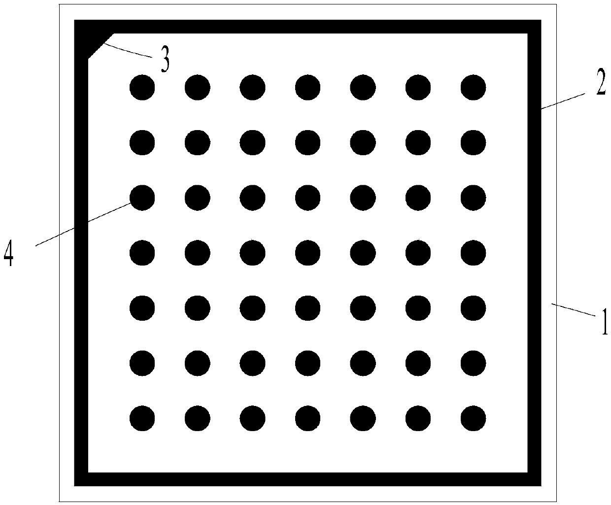

Image

  • Badminton robot camera calibration method
  • Badminton robot camera calibration method
  • Badminton robot camera calibration method

Examples


Embodiment Construction

[0019] The present invention will be further described in detail below in combination with specific embodiments. However, it should not be understood that the scope of the above subject matter of the present invention is limited to the following embodiments, and all technologies realized based on the content of the present invention belong to the scope of the present invention.

[0020] Calibration of the camera itself: an introduction to the binocular system

[0021] In order to calculate the 3D points, we use a binocular system composed of two cameras to achieve 3D reconstruction. In order to keep the binocular system relatively stable, we use carbon rods to fix the two cameras directly together. The hardness and high strength of the carbon rod ensure that the relative positions of the two cameras remain unchanged, and the internal and external parameters of the cameras are kept constant. So as to ensure the accuracy of calculating three-dimensional points.

[0022] The p...


PUM


Abstract

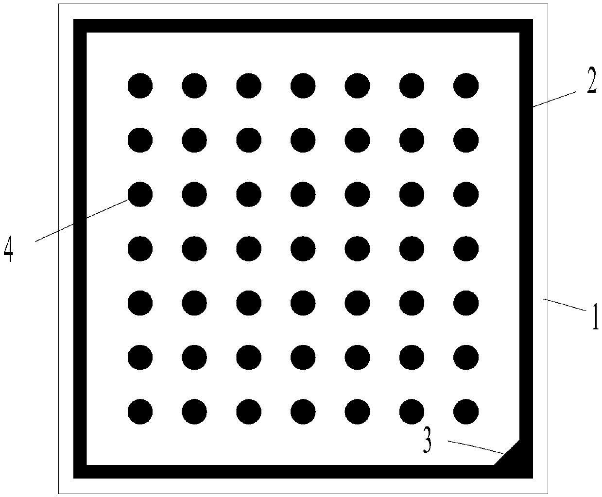
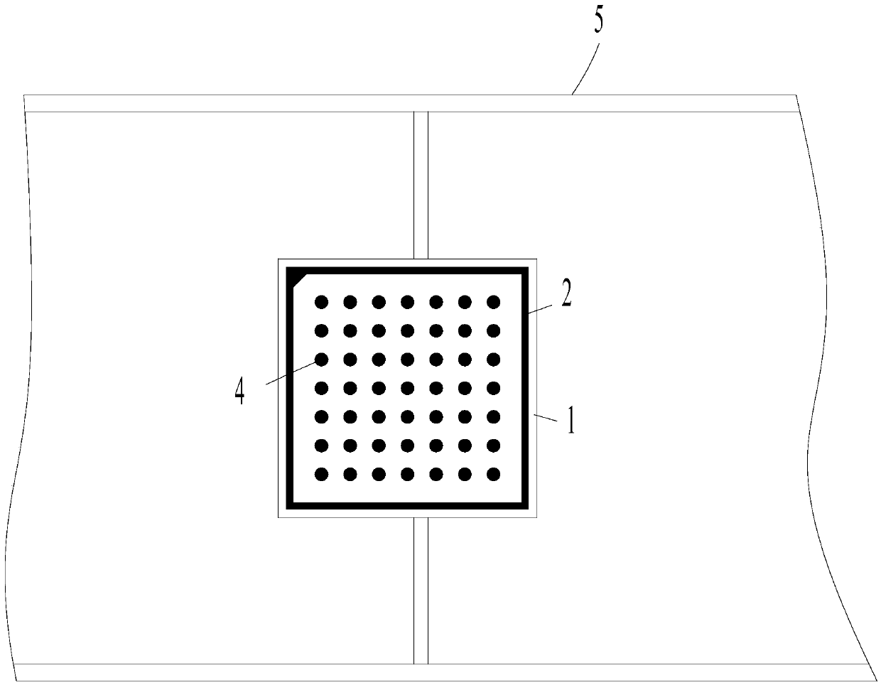
The present invention discloses a badminton robot camera calibration method which comprises a step of using a calibration plate to calibrate the internal and external parameters of cameras, wherein due to the structure of the equal distance and size of the black points of the calibration plate, the two-dimensional position and the orientation information of the calibration plate can be easily identified in an image, a step of establishing the correspondence between the cameras and a real world through a corresponding relation according to physical distance between the black points on the calibration plate, and establishing the equation of the internal parameter, and a step of using left and right cameras to carry out calibration to obtain the internal parameters of the cameras, wherein since the left and right cameras are corresponding to the same calibration plate in left and right images, thus the corresponding relation which is an external parameter matrix between the left and right cameras can be established on the above basis.

Description

[0001] This case claimed the priority of the Chinese invention patent filed on June 17, 2015 with the application number 2015103389533. technical field [0002] The invention relates to the field of badminton robots, in particular to a camera calibration method for a badminton robot. Background technique [0003] In the badminton robot competition, the three-dimensional coordinate system of badminton is established based on the binocular vision camera system, and the coordinates of the binocular vision need to be converted into the world coordinates of the robot. When the position of the robot deviates, use the calibration plate on the robot body. correction. [0004] At present, there is a lack of camera calibration and correction of robot motion position deviation based on this. Contents of the invention [0005] The purpose of the present invention is to overcome the above-mentioned deficiencies in the prior art and provide a camera calibration method for a badminton r...

Claims


Application Information

Patent Timeline
Patent Type & Authority Applications(China)
IPC IPC(8): G06T7/00
CPCG06T2207/30221
Inventor 骆德渊孙锐胡喆贾瑞兴任渊崔巍杰何东流李建华李兴龙刘家桐
Owner 四川新尚人工智能科技有限公司
Learn More