A system architecture construction method
A system architecture and construction method technology, applied in the field of system engineering, can solve problems such as docking difficulties, unusable models, and difficulties in getting started, and achieve the effect of avoiding incomplete consideration of factors
- Summary
- Abstract
- Description
- Claims
- Application Information
AI Technical Summary
Problems solved by technology
Method used
Image
Examples
Embodiment 1
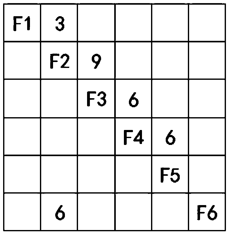
[0038] Taking the flight control system as an example, the controlled object is the rudder surface, which needs to realize the six functions of "sensing the driving command, D / A conversion, calculation, A / D conversion, driving the movement of the actuator and sensitive rudder surface position". The data relationship between them, drawing the EFFBD diagram of the system is as follows figure 1 As shown, among them, F1 represents the perceived driving command, F2 represents the D / A conversion, F3 represents the calculation, F4 represents the A / D conversion, F5 represents the movement of the driving actuator, and F6 represents the position of the sensitive control surface. figure 1 It can be seen that the premise of F1 realization is that the driver manipulates the steering column and the driver manipulates the pedals, the output of which is longitudinal driving displacement signal, lateral driving displacement signal, etc., and the output of F1 is used as the input of F2, and the ...
Embodiment 2
[0053] Similar to Embodiment 1, take the mobile phone to answer the phone as an example. When making a call, the mobile phone needs to have a signal, so it has the function of receiving the operator's signal. In addition, it should also have the function of unlocking the mobile phone, inputting the other party's number, calling the mobile phone to store contacts, and making a call. The function of receiving missed calls and storing them. Take this as an example, specifically as Figure 4 shown.
[0054] first N 2 The construction of the graph will not be described in detail, and then the architecture allocation table is constructed, as shown in Table 3.
[0055] Table 3. Architecture Allocation Table
[0056]
[0057]
[0058] According to the architecture allocation table, it is found that F4, F5, F7, and F8 are all completed by the handset, microphone, memory, and mobile phone chip. F3 and F6 are all implemented by software. One function, and the unlocking function...
Embodiment 3
[0061] Similar to the above embodiment, the main steps are as follows:
[0062]First select the necessary functional requirements for system design from the functional requirements of the system; then draw the system EFFBD diagram according to the necessary functional requirements of the system, and draw the interface relationship between functions in EFFBD combined with the interface requirements. The EFFBD diagram is a functional block diagram drawn in time series of functional occurrences. The functional block diagram is represented by a box plus a serial number, and the data flow between functions is represented by a rounded rectangle plus an arrow, a single arrow represents a data flow, and a double arrow represents a trigger data, that is, only when the data occurs, the function can be executed . If there are multiple functions, the function flow chart can also expand the functions of the system, sub-system and subsystem in a hierarchical manner;
[0063] Second, draw ...
PUM
 Abstract
Description
Claims
Application Information
 - R&D
- Intellectual Property
- Life Sciences
- Materials
- Tech Scout
- Unparalleled Data Quality
- Higher Quality Content
- 60% Fewer Hallucinations
Browse by: Latest US Patents, China's latest patents, Technical Efficacy Thesaurus, Application Domain, Technology Topic, Popular Technical Reports.
© 2025 PatSnap. All rights reserved.Legal|Privacy policy|Modern Slavery Act Transparency Statement|Sitemap|About US| Contact US: help@patsnap.com


