
Empirical mode decomposition-based improved harmonic analysis method

A technology of empirical mode decomposition and analysis method, applied in the field of harmonic analysis method of empirical mode decomposition, which can solve the problems of high parameter requirements, low precision and large error of detection results of analog filter method

Inactive Publication Date: 2016-04-20
HEFEI UNIV OF TECH
View PDF11 Cites 20 Cited by
  • Summary
  • Abstract
  • Description
  • Claims
  • Application Information

AI Technical Summary

Problems solved by technology

[0004] Based on the Fourier transform and a series of improved analysis methods, there are certain spectrum leakage phenomena and fence effects, and it is impossible to locate the time when the transient signal occurs and ends, the algorithm structure is complex, and the circuit hardware requirements are high;
[0005] The analysis method based on wavelet transform, but the wavelet transform often decomposes the low-frequency band, resulting in low resolution of the high-frequency band, which reduces the detection accuracy of high-order harmonics. In addition, wavelet detection largely depends on the selection of wavelet bases, reducing the Algorithmic adaptation;
[0006] The analog filter method has high requirements on circuit component parameters, poor real-time performance, and relatively low accuracy; the detection method based on instantaneous reactive power has large errors in detection results, and the detection algorithm for single-phase circuits is complex and difficult to implement

Method used


Image

  • Empirical mode decomposition-based improved harmonic analysis method
  • Empirical mode decomposition-based improved harmonic analysis method
  • Empirical mode decomposition-based improved harmonic analysis method

Examples


Embodiment example

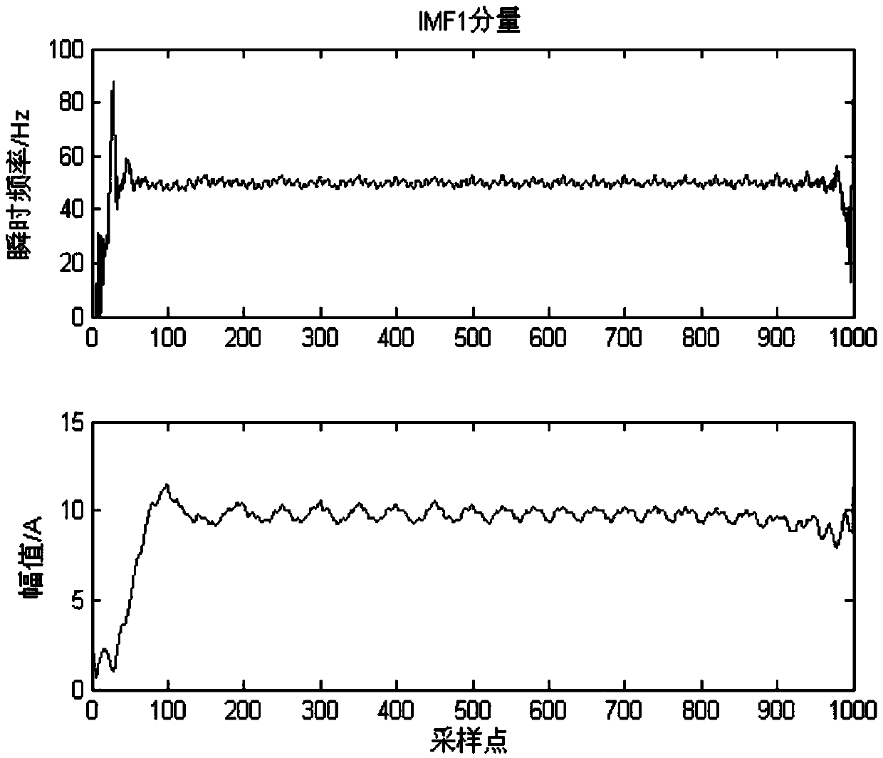
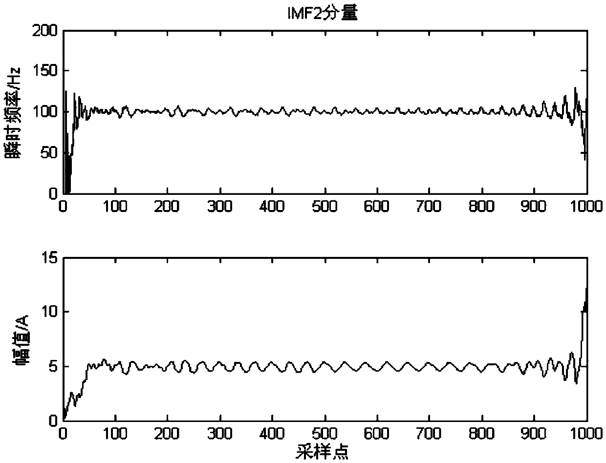
[0058] Set a randomly variable current signal:

[0059] i(t)=10cos(2π*50*t)+5cos(2π*100*t)+4cos(2π*150*t)+6cos(2π*450*t);

[0060] The unit of the current signal is A, of course, a voltage signal can also be selected for analysis, and the unit of the voltage signal is V.

[0061] Such as figure 1 Shown, the harmonic analysis method of the present invention comprises the following steps:

[0062] Step A: The central processing unit sets the sampling period as T=0.001s, performs real-time sampling and quantization on the random variable current signal i(t) to obtain the original signal x[t], where t=1000;

[0063] Step B: The original signal x[t] is decomposed by empirical mode to obtain each IMF modal component, and each IMF modal component is transformed by Hilbert-Huang (HHT) to obtain an instantaneous frequency diagram;

[0064] The steps of empirical mode decomposition of the original signal x[t] are as follows:

[0065] S101: the first screening: interpolate all local ...


PUM


Abstract

The invention relates to an empirical mode decomposition-based improved harmonic analysis method. The analysis method includes the following steps that: a central processor sets a sampling period, performs real-time sampling and quantization on the signals of a power system so as to obtain original signals x [t]; empirical mode decomposition is performed on the original signals x [t], so that IMF modal components can be obtained, and HHT transform is performed on the IMF modal components, so that an instantaneous frequency graph can be obtained; frequency differences between the IMF modal components are calculated, and IMF modal components on which mode mixing begins to occur are found out; all IMF modal components before the occurrence of the mode mixing are removed from the original signals x [t]; spectrum analysis is performed on remaining signals, and frequency band filtering is performed on IMF modal components within double frequency; HHT transform is performed on the filtered IMF modal components, so that an instantaneous frequency and amplitude graph can be obtained. With the empirical mode decomposition-based improved harmonic analysis method of the invention adopted, different characteristics of the signals of the power system can be clearly differentiated from the HHT transform graphs, and an effective and rapid analysis mode can be provided for the harmonic analysis of the power system.

Description

technical field [0001] The invention belongs to the field of harmonic analysis of electric power systems, and in particular relates to an improved empirical mode decomposition harmonic analysis method. Background technique [0002] As the power grid is continuously connected to nonlinear loads, such as large-scale power electronic devices and distributed power sources, the power quality problem at the receiving end of the power grid cannot be ignored, which makes the harmonic components of the power grid increasingly complex, and the randomness and non-stationarity of the harmonic content increase. Power quality and harmonic analysis pose a problem. The existence of harmonics brings various adverse effects to the power system, such as reducing the service life of power equipment, causing malfunction of power system protection devices, increasing power loss in the power grid, and increasing the complexity of power metering. [0003] Aiming at the detection and analysis of po...

Claims


Application Information

Patent Timeline
IPC IPC(8): G01R23/165
CPCG01R23/165
Inventor 陈波陈浩李华储昭碧刘冬梅徐扬
Owner HEFEI UNIV OF TECH
Learn More