A Low Temperature Ultrasonic Vibration Fatigue Experimental System
A technology for ultrasonic vibration and fatigue experiments, applied in the direction of using sonic/ultrasonic/infrasonic waves to analyze solids, instruments, and materials. effect of temperature
- Summary
- Abstract
- Description
- Claims
- Application Information
AI Technical Summary
Problems solved by technology
Method used
Image


Examples
Embodiment 1
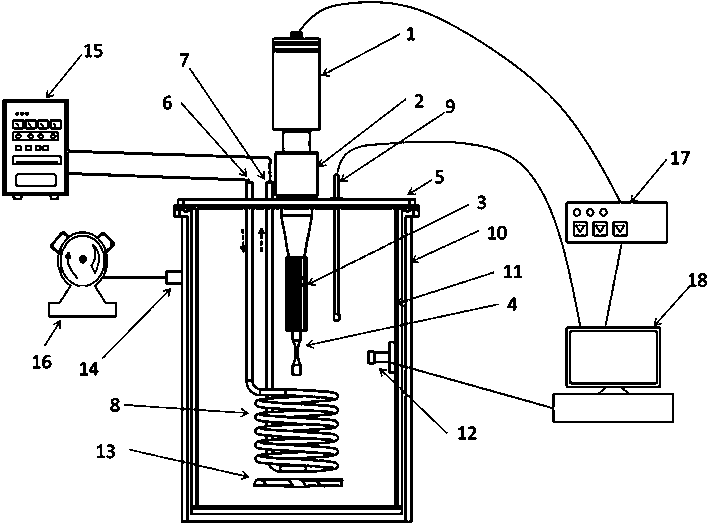
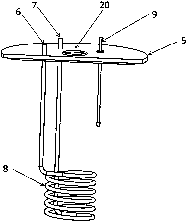
[0037] Such as Figure 1 to Figure 4 As shown, a low-temperature ultrasonic vibration fatigue test system includes a piezoelectric transducer 1 and an ultrasonic signal generator 17, the electric energy input end of the piezoelectric transducer 1 and the AC signal output end of the ultrasonic signal generator 17 Electrically connected, the mechanical vibration output end of the piezoelectric transducer 1 is connected to the test piece 4;
[0038] It also includes a low temperature box, the low temperature box is a closed box structure, the test piece 4 is located in the low temperature box, a cooler 8 is also arranged in the low temperature box, and a cooling device 15 is also provided outside the low temperature box, so The cooling device 15 is connected to the cooler 8 through a pipeline;
[0039] The cooler 8 is a spiral coil structure, and the reciprocating direction of the test piece 4 is located on the axis of the spiral coil structure;
[0040] It also includes a conv...
Embodiment 2
[0047] Such as Figure 1 to Figure 4 As shown, the present embodiment is further limited on the basis of Embodiment 1: since no matter whether single crystal or ceramic material is used in the existing piezoelectric transducer 1, the mechanical deformation displacement obtained is very small, such as only a few microns, In order to amplify the above displacements to obtain more accurate measurement values, a displacement amplifier 2 is connected to the mechanical vibration output end of the piezoelectric transducer 1 , and the test piece 4 is connected to the displacement amplifier 2 . The displacement amplifier 2 realizes the amplification of vibration displacement based on the fact that different parts have different displacements during resonance. The more commonly used shapes are: exponential, conical, and stepped displacement amplifiers.
[0048] Since the piezoelectric transducer 1 and the displacement amplifier 2 both have heat generation during work, in order to avoid...
Embodiment 3
[0054] Such as Figure 1 to Figure 4 As shown, this embodiment is further limited on the basis of any one of the technical solutions provided in the above embodiments: in order to enable this system to realize the vibration fatigue experiment of specimen 4 under low temperature and vacuum environment, and realize vacuum heat insulation at the same time, which is beneficial to the insulation Thermal effect, to improve the temperature control accuracy of the test piece 4, to obtain more accurate low temperature vibration fatigue test value, the vacuum interface 14 is also provided on the low temperature box, and the vacuum interface 14 is connected to a vacuum port located outside the low temperature box through a pipeline. 16 of vacuum pumps. This scheme also has the purpose of reducing the amount of cooling medium and reducing energy consumption.
[0055] As a specific implementation scheme for improving the experimental efficiency of the system, the ultrasonic signal generat...
PUM
| Property | Measurement | Unit |
|---|---|---|
| diameter | aaaaa | aaaaa |
| thickness | aaaaa | aaaaa |
| diameter | aaaaa | aaaaa |
Abstract
Description
Claims
Application Information
 - R&D
- Intellectual Property
- Life Sciences
- Materials
- Tech Scout
- Unparalleled Data Quality
- Higher Quality Content
- 60% Fewer Hallucinations
Browse by: Latest US Patents, China's latest patents, Technical Efficacy Thesaurus, Application Domain, Technology Topic, Popular Technical Reports.
© 2025 PatSnap. All rights reserved.Legal|Privacy policy|Modern Slavery Act Transparency Statement|Sitemap|About US| Contact US: help@patsnap.com