Eureka AIR delivers breakthrough ideas for toughest innovation challenges, trusted by R&D personnel around the world.

A cable for electric vehicle charging pile and its manufacturing method

A technology of electric vehicles and production methods, which is applied in the field of cables, can solve problems such as poor pullability and bending resistance, and achieve the effects of improving tensile and compressive resistance, improving service life and safety, and high flexibility

Active Publication Date: 2017-11-17
上海朗达电缆(集团)有限公司
View PDF4 Cites 0 Cited by
  • Summary
  • Abstract
  • Description
  • Claims
  • Application Information

AI Technical Summary

Problems solved by technology

[0003] The purpose of the present invention is to provide an improved cable for electric vehicle charging pile and its manufacturing method, which can overcome some shortcomings of the prior art in terms of poor tensile properties and bending resistance

Method used


Image

  • A cable for electric vehicle charging pile and its manufacturing method
  • A cable for electric vehicle charging pile and its manufacturing method
  • A cable for electric vehicle charging pile and its manufacturing method

Examples


Embodiment 1

[0026] The manufacturing process of the present invention is as follows:

[0027] 1. Conductor stranding.

[0028] For the charging core and signal core, flexible fine copper wire conductors are used, and the conductor diameter is 0.15mm-0.2mm. In order to increase the bending resistance and tensile performance of the conductor, three steel wires of the same specification are added to make the conductor structure dense, thereby reducing outer diameter, reducing costs.

[0029] 2. Insulation extruded package.

[0030] The insulating layer is insulated with ethylene propylene rubber. The long-term allowable working temperature of the cable is -40~125°C. It is a saturated non-polar material with high aging resistance: ozone resistance and high thermal stability. (The weight loss temperature of natural rubber is 315°C in a nitrogen environment. Styrene butadiene rubber is 391 ℃, EPDM rubber is 485 ℃) good heat aging resistance, excellent weather resistance, excellent chemical r...

Embodiment 2

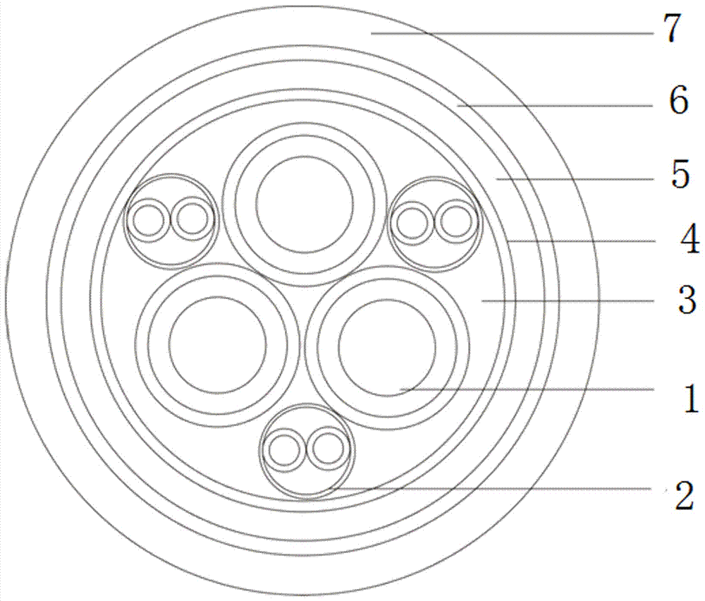
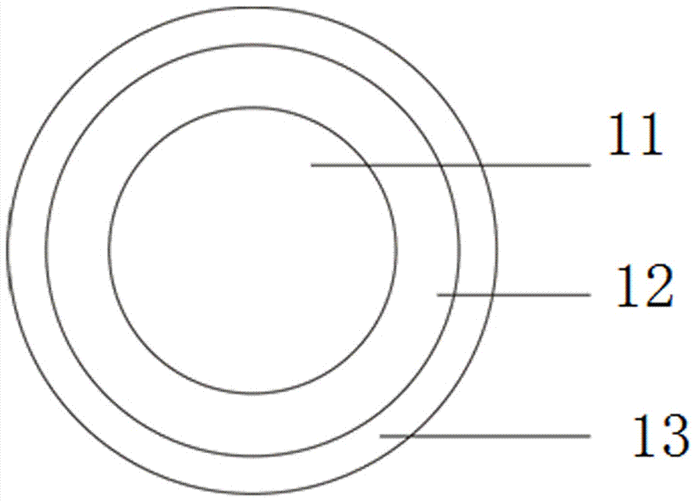
[0044] The first choice is to make the charging wire core, wrap the charging insulation layer around the copper wire conductor, and then wrap a charging slip layer outside the charging insulation layer, wherein the charging conductor is a copper wire conductor with a conductor diameter of 0.18mm, and the charging wire core The charging insulation layer is made of ethylene propylene rubber, the thickness of the charging insulation layer is 0.10-0.15mm, the charging slip layer is wrapped with polyester tape, and the thickness of the charging slip layer is 0.19mm;

[0045] Next, make the signal core, using two copper wire conductors with the same diameter as a group, each copper wire conductor is wrapped with a signal insulation layer on the surface, and then a shielding layer is wrapped around the signal insulation layer of the two copper wire conductors The two sets of signal conductors are made of copper wire conductors wrapped around the outside of the signal insulation layer,...


PUM

PropertyMeasurementUnit
thicknessaaaaaaaaaa
diameteraaaaaaaaaa
thicknessaaaaaaaaaa

Abstract

The invention relates to a cable for electric vehicle charging pile, characterized in that: the cable is composed of an outer cladding and an inner core, the inner core is composed of a charging wire core and a signal wire core, and the connection between the charging wire core and the signal wire core is The quantity ratio is 1:1; each charging core is composed of a charging conductor, a charging insulation layer outside the conductor and a charging slip layer; each signal core is composed of two sets of signal conductors and a shielding layer; outsourcing The layer is wrapped in turn by an outer slip layer, an isolation layer, a braided layer and a sheath layer. The present invention is equipped with a charging wire core and a signal wire core at the same time, which can be used as a connection charging function between the electric vehicle charging equipment and the charging interface, and at the same time has the control signal transmission function for charging saturation, safety warning, etc., and has high flexibility. The minimum bending radius can reach 5xOD (nominal diameter of the cable), which is easy to install and use. Good tensile and bending resistance, the use of slip layer structure increases the bending performance.

Description

technical field [0001] The invention relates to the technical field of cables, in particular to a cable used for electric vehicle charging piles and a manufacturing method thereof. Background technique [0002] At present, with the development of the automobile industry and the improvement of people's living standards, people's demand and use of cars are increasing, and the exhaust gas emitted by cars is also increasing rapidly. The research and development of new environmentally friendly and energy-saving vehicles has become an important topic at present, and the development of new energy electric vehicles has become the first choice. Therefore, the development of new electric vehicle charging cables has become an urgent problem in the cable industry. The charging pile cable is in a state of frequent dragging and moving during use, and the frequently bent core conductor is easy to break and is vulnerable to damage such as being crushed by a car. higher requirements. Con...

Claims


Application Information

Patent Timeline
Patent Type & Authority Patents(China)
IPC IPC(8): H01B7/04H01B7/18H01B7/17H01B7/22
CPCH01B7/04H01B7/17H01B7/18H01B7/22Y04S30/12Y02T90/167
Inventor 王浩淼王成忠刘源
Owner 上海朗达电缆(集团)有限公司
Why Eureka
Eureka Blog
Learn More