
a shotgun

A shotgun and gun body technology, which is applied in the field of shotguns, can solve the problems of reducing production efficiency, preventing jumping damage, and preventing jumping loss, and achieves the effects of reducing production costs, preventing loss, and increasing gaps

Active Publication Date: 2017-09-26
RIZHAO BROTHER MACHINERY CO LTD
View PDF9 Cites 0 Cited by
  • Summary
  • Abstract
  • Description
  • Claims
  • Application Information

AI Technical Summary

Problems solved by technology

[0002] For the existing Winchester M1300-20GA shotgun, it has the following deficiencies in use and in the manufacturing process: 1. When it is necessary to disassemble the limiter rod, at first the locking nut will be taken off, and then the The anti-bounce cap is taken out from the magazine barrel, and then the guide shaft can only be taken out from the magazine barrel. It is made of high-quality rubber material, and when taking out the anti-bounce cap, it is usually pried out with a tool such as a screwdriver, which not only easily causes damage to the anti-bump cap, but also is easy to be affected by the spring force after being removed. Being bounced off, the anti-jump cap is lost, and it also increases the difficulty of installation, which brings great inconvenience to the user; 2. In order to prevent the locking nut at the front end of the magazine barrel from automatically loosening and falling off during use Therefore, the support ring below the front end of the gun barrel is provided with a limit mechanism specially used to limit the lock nut. This mechanism is composed of withstanding, spring and screw. Mechanisms are all relatively small, so it is just very cumbersome to process in the production process, which reduces the efficiency of production; 3, the lock groove on the barrel seat in the prior art is closely matched with the lock catch on the gun movement heart, so for The processing precision of the spiral groove on the bolt frame will be very high, otherwise the lock and the lock groove will not cooperate. For this high-precision processing, not only special processing equipment is required, but also high-tech workers are required to complete the processing. , but in reality it is difficult to find such suitable skilled workers, which not only affects the efficiency of product production, but also increases the cost of enterprise production

Method used


Image

  • a shotgun
  • a shotgun
  • a shotgun

Examples


Embodiment Construction

[0016] The present invention will be described in detail below in conjunction with the accompanying drawings.

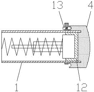
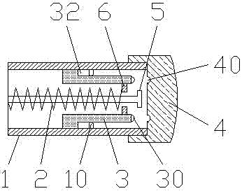
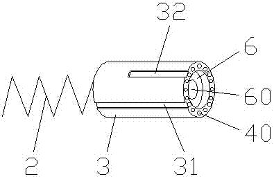
[0017] As shown in the figure, a shotgun includes a gun body, a bolt locking mechanism located in the gun body, a magazine barrel 1 located below the gun body, and a locking screw located at the front end of the magazine barrel 1. The cap 4 is characterized in that: a limit button 10 is provided on the inner wall of the magazine barrel 1, a guide shaft 3 and a spring 2 are respectively arranged in the magazine barrel 1, and the spring 2 is located on the guide shaft 3 The end of the guide shaft 3 is respectively provided with a through groove 31 and a limit groove 32, and a perforation 60 is provided in the guide shaft 3, and the perforation 60 is used to place the limiter rod 5, the limit groove 32, the through The slot 31 and the stop buckle 10 are symmetrically arranged, and the difference between the through slot 31 and the stop slot 32 is 90 degrees, so that whe...


PUM


Abstract

The invention discloses a novel shotgun and belongs to the field of guns. The novel shotgun comprises a gun body, a gun locking mechanism located in the gun body, a cartridge cylinder located below the gun body and a lock nut located at the front end of the cartridge cylinder. The novel shotgun is characterized in that limiting buckles are arranged on the inner wall of the cartridge cylinder; a guide shaft and a spring are arranged in the cartridge cylinder; the spring is located at the tail end of the guide shaft; through grooves and limiting grooves are formed in the outer portion of the guide shaft; and a through hole is formed in the guide shaft. According to the novel shotgun, many defects in a traditional shotgun are overcome, the improved shotgun is easy and convenient to use, the difficulty of the production technology and manufacture is lowered, and the production cost of an enterprise is greatly saved.

Description

technical field [0001] The present invention relates to a firearm device, especially a hunting rifle. Background technique [0002] For the existing Winchester M1300-20GA shotgun, it has the following deficiencies in use and in the manufacturing process: 1. When it is necessary to disassemble the limiter rod, at first the locking nut will be taken off, and then the The anti-bounce cap is taken out from the magazine barrel, and then the guide shaft can only be taken out from the magazine barrel. It is made of high-quality rubber material, and when taking out the anti-bounce cap, it is usually pried out with a tool such as a screwdriver, which not only easily causes damage to the anti-bump cap, but also is easy to be affected by the spring force after being removed. Being bounced off, the anti-jump cap is lost, and it also increases the difficulty of installation, which brings great inconvenience to the user; 2. In order to prevent the locking nut at the front end of the maga...

Claims


Application Information

Patent Timeline
Patent Type & Authority Patents(China)
IPC IPC(8): F41B7/00F41A3/66F41A3/00
CPCF41A3/00F41A3/66F41B7/003
Inventor 时百峰
Owner RIZHAO BROTHER MACHINERY CO LTD
Learn More