Automatic residue poking method and device for wind distribution plate of biomass circulating fluidized bed boiler

A technology of circulating fluidized bed and air distribution plate, which is applied in the field of automatic slagging of biomass circulating fluidized bed boiler air distribution plate, which can solve problems such as blockage of biomass boiler slag discharge pipe, improve fluidization effect and ensure stability Operation, safety and reliability, and the effect of eliminating influence

Active Publication Date: 2016-04-13
WUHAN KAIDI ENG TECH RES INST CO LTD
View PDF8 Cites 6 Cited by
  • Summary
  • Abstract
  • Description
  • Claims
  • Application Information

AI Technical Summary

Problems solved by technology

[0007] The purpose of the present invention is to provide a method and device for automatically removing slag from the air distribution plate of a biomass circulating fluidized bed boiler. The method and device can effectively solve the problem of blockage of the slag discharge pipe of the biomass boiler and overcome the traditional manual method of removing slag. A series of safety and economic defects caused by slag

Method used


Image

  • Automatic residue poking method and device for wind distribution plate of biomass circulating fluidized bed boiler
  • Automatic residue poking method and device for wind distribution plate of biomass circulating fluidized bed boiler
  • Automatic residue poking method and device for wind distribution plate of biomass circulating fluidized bed boiler

Examples


Embodiment Construction

[0040] The device and method of the present invention will be further described in detail below in conjunction with the accompanying drawings and specific embodiments.

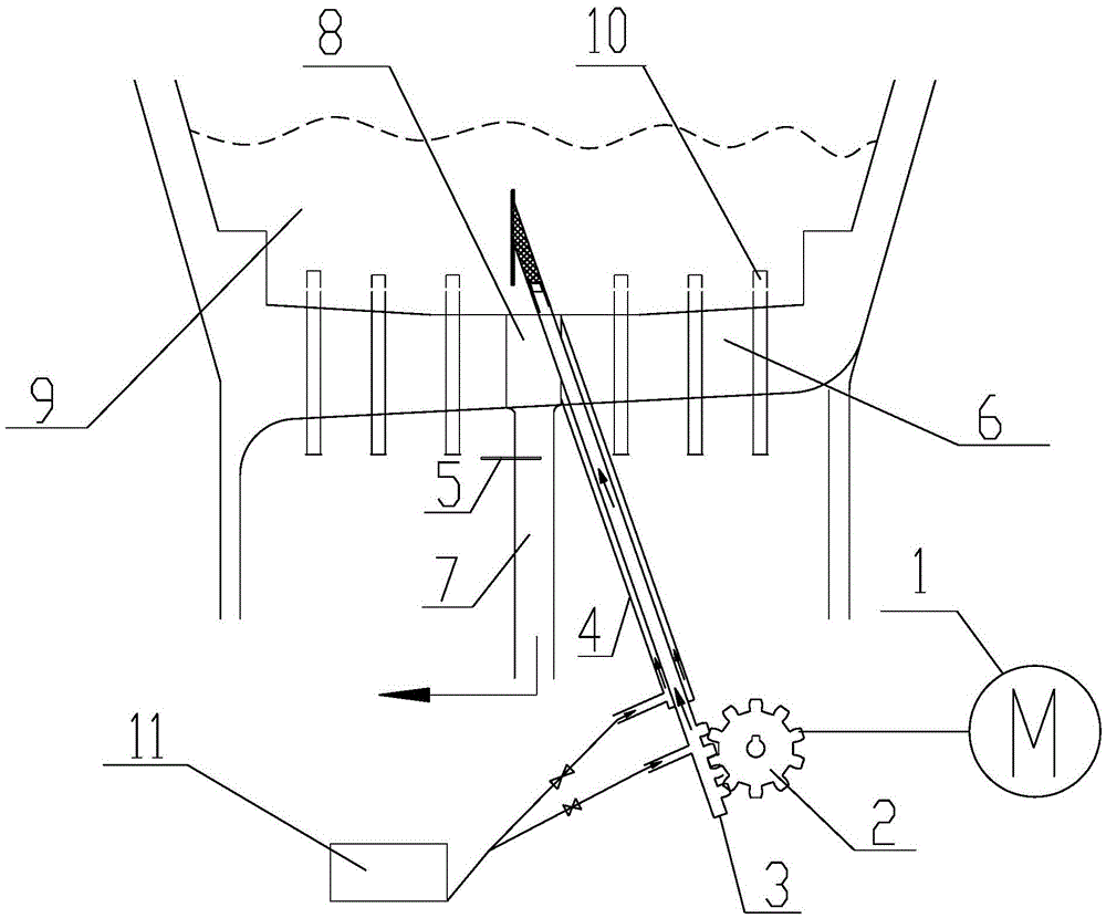
[0041] The automatic slagging device of the air distribution plate of the biomass circulating fluidized bed boiler shown in the figure is installed at the slag discharge hole 8 of the air distribution plate 6 of the boiler, on the side of the slag discharge pipe 7 below the slag discharge hole 8 . It has an outer sleeve 4 arranged obliquely to the slag discharge pipe 7. The inclination angle of the outer sleeve 4 relative to the slag discharge pipe 7 is about 22-24°. The side wall openings are connected as a whole, and its structure is simple and compact, occupying very little space.

[0042] Axially telescopic fluidizing air duct 3 is installed in the inner cavity of outer casing 4, and the upper end of the fluidizing air duct 3 is welded with a slag breaking head 31. The shape of the opening of the side wal...


PUM


Abstract

The invention discloses an automatic residue poking method and device for a wind distribution plate of a biomass circulating fluidized bed boiler. According to the technical scheme of the automatic residue poking method and device, an outer sleeve connected with a side wall opening of a residue discharging hole is arranged at the side wall opening of the residue discharging hole of the wind distribution plate and inclines relative to a residue discharging pipe, and a telescopic fluidization wind pipe with a residue poking head and fluidization wind outlets is arranged in an inner cavity of the outer sleeve. When the boiler operates normally, the residue poking head extends into a bed material above the residue discharging hole, and fluidization wind is injected to the periphery of the residue discharging hole through the fluidization wind outlets. When the residues need to be discharged from the boiler, the residue poking head draws back into the inner cavity of the outer sleeve so that the top of the residue poking head can be matched with the side wall opening of the residue discharging hole in a sealed manner. When the residues are blocked in the boiler in the discharging process, the residue poking head stretches out and draws back in the bed material above the residue discharging hole to finish physical stirring, large blocks of residues are broken, and meanwhile ash near the residue discharging hole can be continuously blown by injecting the fluidization wind, so that automatic residue poking is achieved. By the adoption of the automatic residue poking method and device, the defects brought by traditional manual residue poking are effectively overcome.

Description

technical field [0001] The invention relates to the technical field of circulating fluidized bed boiler combustion, in particular to a method and a device for automatically poking slag through an air distribution plate of a biomass circulating fluidized bed boiler. Background technique [0002] Today's society is facing the double test of huge energy and environmental problems, and finding a renewable alternative energy source has become an urgent problem to be solved. Biomass fuel is renewable, can be directly stored and transported, and CO 2 Its development and utilization have attracted widespread attention from all over the world due to its advantages such as small emissions. At present, the available biomass fuels mainly include: various agricultural wastes such as rice husks, cotton stalks, rape stalks and corn stalks, various forestry wastes such as twig firewood, wood scraps, tree roots, etc., as well as medicinal residues, Construction formwork, municipal waste, e...

Claims


Application Information

Patent Timeline
IPC IPC(8): F23C10/24
CPCF23C10/24
Inventor 黄志军蔡海燕王敬叶普海
Owner WUHAN KAIDI ENG TECH RES INST CO LTD
Why Eureka
Try Eureka