Vibration eliminating device and switching apparatus
A cylinder block and pressure relief valve technology, applied in mechanical equipment, protection switches, emergency protection devices, etc., can solve problems such as closing and bouncing of moving contacts, and achieve the effects of promoting deceleration, improving efficiency, and improving dynamic performance
- Summary
- Abstract
- Description
- Claims
- Application Information
AI Technical Summary
Problems solved by technology
Method used
Image
Examples
Embodiment approach 1
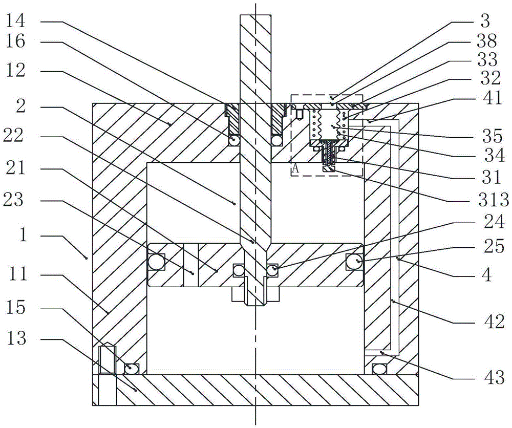
[0044] A kind of damping device of the present invention, as figure 1As shown, it includes a cylinder body 1, a piston mechanism 2, a pressure relief device 3 and a channel 4. The cylinder body 1 includes a first end cover 12, a cylinder barrel 11 and a second end cover 13, the first end cover 12 is sealed and fixed on the top end of the cylinder barrel 1, further, the first end cover 12 and the cylinder The barrel 1 is integrally formed; the second end cover 13 is fixed on the bottom end of the cylinder barrel 1 by bolts, and the second end cover 13 and the bottom end of the cylinder barrel 1 are sealed by the first sealing ring 15 . The piston mechanism 2 includes a piston 21 and a piston rod 22 . The piston 21 is arranged inside the cylinder 1 , and the side surface of the piston 21 and the inner surface of the cylinder 11 are sealed by a fourth sealing ring 25 , and the piston 21 can slide relative to the cylinder 11 along the axial direction. The piston 21 divides the i...
Embodiment approach 2
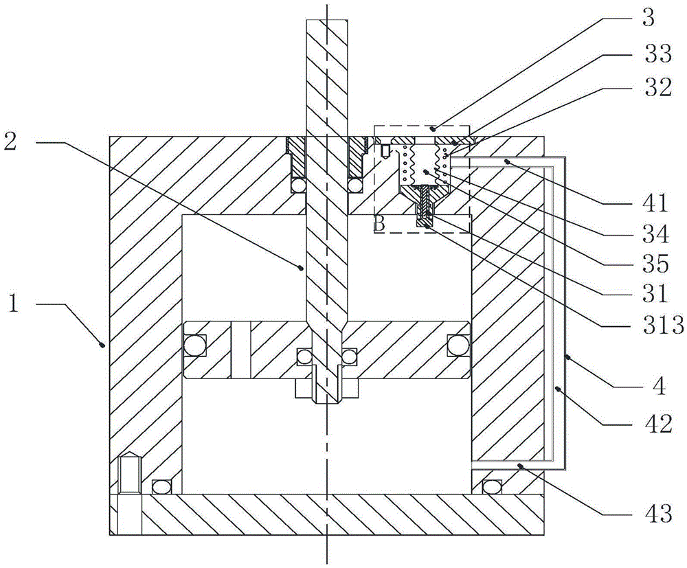
[0056] The difference between Embodiment 2 and Embodiment 1 is only: figure 2 As shown, the channel 4 includes a first channel 41 , a second channel 42 and a third channel 43 . The first channel 41 is built in the first end cover 12 and is in sealing communication with the pressure relief chamber 35 of the pressure relief device, distributed along the radial direction of the first end cover 12; the second channel 42 is arranged outside the cylinder 1, Distributed along the axial direction of the cylinder 11; the third channel 43 is arranged in the cylinder wall of the cylinder 11 and is located on the side of the second end cover 13 and is in sealing communication with the second chamber, distributed along the radial direction of the cylinder 11 . The first channel 41 , the second channel 42 and the third channel 43 are sequentially sealed and communicated with each other.
Embodiment approach 3
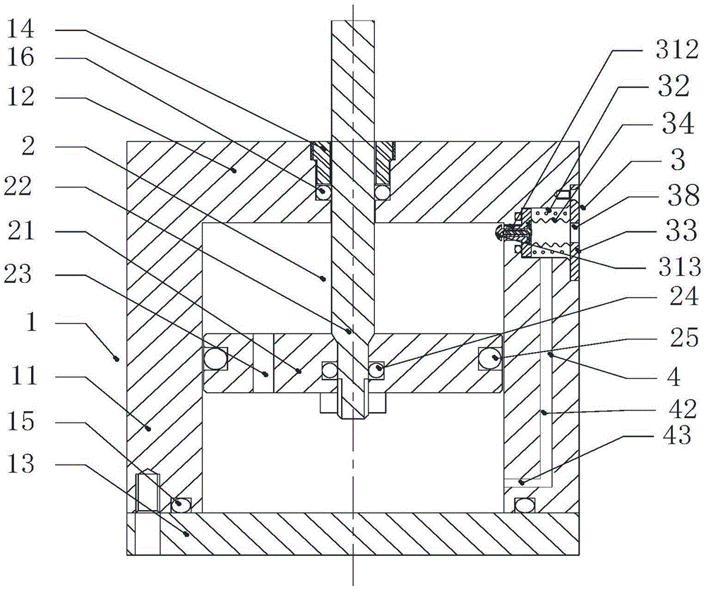
[0058] The difference between Embodiment 3 and Embodiment 1 is only: image 3 As shown, the pressure relief device 3 is assembled on the upper end of the cylinder wall of the cylinder 11 , that is, on the side of the first end cover 12 . The pressure relief chamber 35 of the pressure relief device 3 is arranged on the upper end of the cylinder wall of the cylinder 11, which is composed of a bottom wall and a side wall, and the top opening is opened at the outer end of the cylinder 11. Here, the pressure relief device 3 The axis direction determines the top and bottom of the spatial orientation of the pressure relief device 3, and the direction away from the vibration damping device is the top. The end of the stem of the pressure relief valve core 31 is inside the valve seat hole 37 , that is, the end of the stem of the valve core does not protrude from the inner surface of the cylinder 11 . The built-in telescopic rod 313 of the pressure relief valve core 31 extends into the ...
PUM
 Abstract
Description
Claims
Application Information
 - Generate Ideas
- Intellectual Property
- Life Sciences
- Materials
- Tech Scout
- Unparalleled Data Quality
- Higher Quality Content
- 60% Fewer Hallucinations
Browse by: Latest US Patents, China's latest patents, Technical Efficacy Thesaurus, Application Domain, Technology Topic, Popular Technical Reports.
© 2025 PatSnap. All rights reserved.Legal|Privacy policy|Modern Slavery Act Transparency Statement|Sitemap|About US| Contact US: help@patsnap.com


