Tin-liquid-impurity filtering apparatus

An impurity filtration and tin liquid technology, applied in the field of tin liquid impurity filtering devices, can solve the problems of manipulating artificial health threats and low efficiency, and achieve the effect of avoiding close contact with tin liquid

Inactive Publication Date: 2016-04-13
CHANGGE HONGLIANG ELECTRIC APPLIANCE FACTORY
View PDF0 Cites 2 Cited by
  • Summary
  • Abstract
  • Description
  • Claims
  • Application Information

AI Technical Summary

Problems solved by technology

[0002] After the tin block is melted, most of the impurities float on the top of the liquid. At present, the treatment method is to manually skim off the floating impurities on the surface, and then the melted tin liquid releases a variety of harmful gases at high temperature. Contact has a very big threat to the health of manipulators. This method of manual removal of impurities is inefficient, and there is more tin liquid in the removal of impurities.

Method used


Image

  • Tin-liquid-impurity filtering apparatus

Examples


Embodiment Construction

[0009] The present invention will be further explained below in conjunction with the drawings.

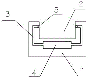
[0010] Such as figure 1 As shown, a tin liquid impurity filtering device includes a tin liquid container 1. The center part of the tin liquid container 1 is a tin liquid accommodating cavity 2. The tin liquid accommodating cavity 2 is provided with an impurity shunt pipe 3 The impurity distribution pipeline 3 leads to the impurity storage cavity 4 at the bottom, and the impurity distribution pipeline 3 is provided with an electromagnetic switch 5.

[0011] The tin liquid impurity filter device with such a structure has the advantages of safety and high efficiency.


PUM


Abstract

The invention relates to a tin-liquid-impurity filtering apparatus, which is used for filtering impurities from a tin liquid. The apparatus comprises a tin-liquid containing device, the center part of which is provided with a tin-liquid containing chamber. An impurity shunting pipeline is arranged on the tin-liquid containing chamber, leads to an impurity-collecting chamber arranged at the bottom of the tin-liquid containing device, and is provided with an electromagnetic switch. The tin-liquid-impurity filtering apparatus has advantages of safety and high efficiency.

Description

Technical field [0001] The invention relates to a tin liquid impurity filtering device, which is used for filtering impurities in the tin liquid. Background technique [0002] In the molten tin, most of the impurities float on the top of the liquid. At present, the treatment method for it is to manually skim off the floating impurities on the surface, and then the molten tin releases a variety of harmful gases at high temperatures. Exposure is a great threat to the health of the manipulator. This method of manual removal of impurities is inefficient, and there is more tin liquid in the removal of impurities. Summary of the invention [0003] The technical problem to be solved by the present invention is to provide an efficient and safe tin liquid impurity filtering device. [0004] In order to solve the above problems, a tin liquid impurity filter device of the present invention includes a tin liquid container. The center part of the tin liquid container is a tin liquid containing ...

Claims


Application Information

Patent Timeline
Patent Type & Authority Applications(China)
IPC IPC(8): C22B25/08C22B9/02
CPCY02P10/20
Inventor 王红亮
Owner CHANGGE HONGLIANG ELECTRIC APPLIANCE FACTORY
Why Eureka
Try Eureka