
Back support device of plate shearing machine

A shearing machine and material support technology, which is applied in the direction of shearing devices, shearing machine accessories, shearing machine equipment, etc., can solve the problems of positioning accuracy, impact on shearing rhythm, loss, etc., and achieve geometric accuracy and improve The effect of shearing quality and less distortion

Active Publication Date: 2016-04-13
GUANGZHOU SHIPYARD INTERNATIONAL LTD
View PDF9 Cites 15 Cited by
  • Summary
  • Abstract
  • Description
  • Claims
  • Application Information

AI Technical Summary

Problems solved by technology

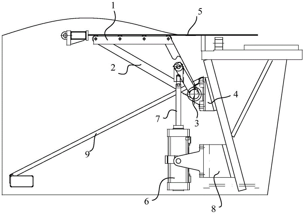
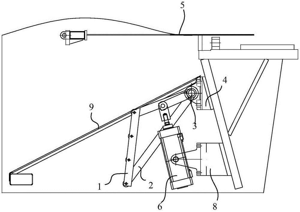
[0003] When cutting, in order to avoid the collision between the support frame 1 and the upper scissors, the support frame 1 should be reset before the shearing action starts. After the reset, the sheet 5 will sag and bend due to the loss of support under the action of gravity. There will be different degrees of distortion during the process; the reset speed of the support arm 2 is difficult to control, and the fast will bring a large impact, and the slow will affect the shearing beat; when continuously cutting large workpieces, the previous plate When the material 5 fails to slide out of the unloading plate 9 completely, if the material 5 is not removed and the rear material supporting device is continued to be used, when the material support 1 swings downward after completing the positioning function again, the material 5 will be pressed. If it is damaged, it will cause loss, and even damage the machine in severe cases; the support frame 1 is welded on the torsion shaft 3 by several sets of support arms 2. Due to the influence of assembly errors and welding deformation, it is difficult to ensure that the support arms 2 are on the same plane. , which is not conducive to the realization of full contact support and affects the positioning accuracy

Method used


Image

  • Back support device of plate shearing machine
  • Back support device of plate shearing machine
  • Back support device of plate shearing machine

Examples


Embodiment Construction

[0026] The technical solutions of the present invention will be further described below in conjunction with the accompanying drawings and through specific implementation methods.

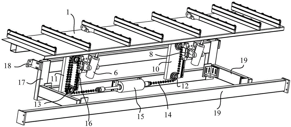
[0027] Such as image 3 As shown, a material supporting device for a shearing machine includes a synchronous lifting mechanism and a material support frame 1 that can be lifted and lowered with the synchronous lifting mechanism. The synchronous lifting mechanism includes two lifting seat assemblies, and two lifting seat assemblies Under the action of the synchronous lifting mechanism, the support frame 1 can be raised and swung to a horizontal state during the material support process, and the support frame 1 can be horizontally lowered at the same speed as the shearing plate during the shearing process Avoid the collision between the support frame 1 and the upper scissors, and can support the sheet material, so that the geometric accuracy of the sheared workpiece is greatly improved, the sheet mate...


PUM


Abstract

The invention discloses a back support device of a plate shearing machine, and relates to the technical field of plate shearing machines. The back support device of the plate shearing machine comprises a synchronous lifting mechanism, and a support frame capable of lifting along with the synchronous lifting mechanism; the synchronous lifting mechanism includes two lifting base assemblies; and the two lifting base assemblies can enable the support frame to ascend and swing to a horizontal state in the support process under the effect of the synchronous lifting mechanism, can enable the horizontal descending speed of the support frame to be the same with the plate shearing speed in the shearing process, and can realize swing unloading of the support frame in the unloading process. The back support device of the plate shearing machine, proposed by the invention, can enable the ascending speed of the support frame to be the same with the plate shearing speed, can prevent the support frame from being collided with an upper scissor, can support a plate, can reduce the distortion of the plate, improves the plate shearing quality, adopts a modular design, can be wholly manufactured, can be mounted on different plate shearing machines, is convenient for installation, and is stronger in practicability.

Description

technical field [0001] The invention relates to the technical field of shearing machines, in particular to a rear material supporting device of a shearing machine. Background technique [0002] The existing supporting device of the shearing machine is mainly based on the positioning type (such as figure 1 As shown), the support frame 1 is made by welding several support arms 2 on a torsion shaft 3, the two ends of the torsion shaft 3 are installed and connected with the bearing 4, and the middle fulcrum of the cylinder 6 is installed on the cylinder. On the seat 8, the cylinder piston rod 7 is hinged with the support arm 2 of the support frame 1. When working, the cylinder piston rod 7 is stretched out, so that the support frame 1 swings to a horizontal position, and then the material is fed and positioned. After the plate 5 is pressed by the compression cylinder, the support frame 1 is reset to the unloading state (such figure 2 shown), then the upper knife rest moves do...

Claims


Application Information

Patent Timeline
IPC IPC(8): B23D33/00B23D15/06
CPCB23D15/06B23D33/00
Inventor 邓锋华陈尚贵廖研
Owner GUANGZHOU SHIPYARD INTERNATIONAL LTD
Learn More