
Solar wing/antenna unfoldable supporting truss and assembly adjustment method thereof

An adjustable support truss technology, applied in the field of aerospace vehicles, can solve the problems of frequent disassembly and assembly, complicated assembly and adjustment process, and low installation and adjustment efficiency, and achieve the effects of high installation and adjustment efficiency, reducing the number of rods, and improving the folding ratio

Active Publication Date: 2016-04-06
SHANGHAI AEROSPACE SYST ENG INST
View PDF5 Cites 16 Cited by
  • Summary
  • Abstract
  • Description
  • Claims
  • Application Information

AI Technical Summary

Problems solved by technology

[0005] c. In the process of ground integration and test debugging, the length of the rod is usually adjusted by increasing or decreasing the adjustment shims of different thicknesses. The rod must be disassembled and assembled every time it is adjusted, which makes the disassembly and assembly frequent, the installation and adjustment process is complicated, and the installation and adjustment efficiency is high. Low

Method used


Image

  • Solar wing/antenna unfoldable supporting truss and assembly adjustment method thereof
  • Solar wing/antenna unfoldable supporting truss and assembly adjustment method thereof
  • Solar wing/antenna unfoldable supporting truss and assembly adjustment method thereof

Examples


Embodiment Construction

[0041] The invention will be described in more detail hereinafter with reference to the accompanying drawings showing embodiments of the invention. However, this invention may be embodied in many different forms and should not be construed as limited to the embodiments set forth herein. Rather, these embodiments are provided so that this disclosure will be thorough and complete, and will fully convey the scope of the invention to those skilled in the art. In these drawings, the size and relative sizes of layers and regions may be exaggerated for clarity.

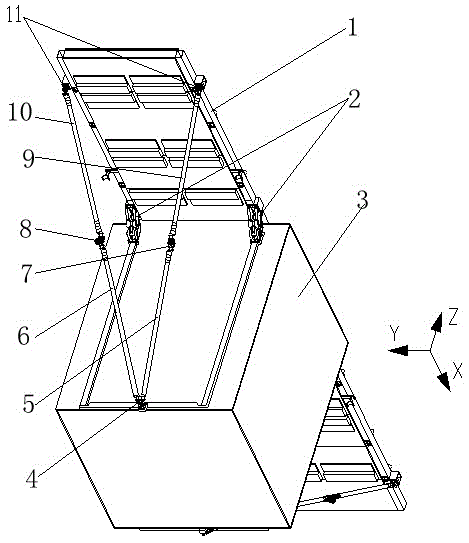
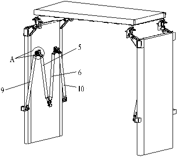
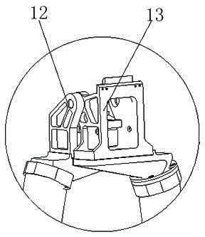
[0042] Please refer to Figure 1-4 , the present invention provides a solar wing / antenna expandable support truss, including a first support rod 5, a second support rod 6, a third support rod 9 and a fourth support rod 10; one end of the solar wing / antenna 1 passes through the plate The inter-panel hinge 2 is connected to the satellite platform 3, and the other end is connected to the satellite platform 3 through a support...


PUM


Abstract

The invention discloses a solar wing / antenna unfoldable supporting truss. The solar wing / antenna unfoldable supporting truss includes a first supporting rod, a second supporting rod, a third supporting rod and a fourth supporting rod. According to the solar wing / antenna unfoldable supporting truss of the invention, a truss rod system is optimized; the unfolding structure of an existing mechanism is simplified; the number of rod components can be decreased; a V-shaped oblique supporting type structure is adopted, so that the support stiffness of the solar wing / antenna unfoldable supporting truss in various spatial directions can be increased; inter-rod hinges are obliquely folded crossing type hinges, and therefore, the enveloping size of the folded truss rod system can be decreased, and the folding ratio of the supporting truss can be improved. The invention also provides an assembly adjustment method of the solar wing / antenna unfoldable supporting truss. With the method adopted, the rod components are not required to be dissembled and assembled in an installation and adjustment process. The method has the advantages of simplicity, convenience, easiness in implementation and high installation and adjustment efficiency.

Description

technical field [0001] The invention relates to the technical field of aerospace vehicles, in particular to a solar wing / antenna expandable support truss and an assembly adjustment method thereof. Background technique [0002] At present, there are many researches and applications on the expandable mechanism of the satellite solar wing at home and abroad, and there is no special precision requirement after the solar wing is deployed in orbit; and the SAR flat panel antenna has a direct impact on the electrical performance of the antenna due to the shape and surface accuracy of the antenna after deployment. It has a great relationship with its imaging quality. In order to ensure that the SAR antenna maintains a relatively high rigidity after being deployed in orbit, a rod system support scheme is usually used on the back of the antenna. The Canadian RADARSAT satellite is a typical application in foreign countries. The development of radar satellites in China started relativel...

Claims


Application Information

Patent Timeline
Patent Type & Authority Applications(China)
IPC IPC(8): H01Q1/08
CPCH01Q1/08
Inventor 李波杜江华瞿佳蔚
Owner SHANGHAI AEROSPACE SYST ENG INST
Learn More