
A fully hydraulic in-hole reaction force mechanism for vibrators in wells

A technology of reaction force mechanism and full hydraulic pressure, applied in the field of reaction force mechanism in holes, can solve the problems of inability of large mechanical equipment to carry out operations and large volume, and achieve the advantages of strong integrity, reduced complexity, and reduced weight and volume. Effect

Active Publication Date: 2017-11-03
JILIN UNIV +2
View PDF4 Cites 0 Cited by
  • Summary
  • Abstract
  • Description
  • Claims
  • Application Information

AI Technical Summary

Problems solved by technology

[0002] At present, the vibrator is an important part of the seismic exploration system. The vibrator is a non-explosive source that is widely used. Since the traditional large-scale vibrator uses its own weight to provide the shock reaction force, most of them are vehicle-mounted vibrators. Its volume is large, and large-scale machinery and equipment cannot go up to carry out operations when exploring in mountainous areas. Based on the disadvantages of traditional vibrator, placing the vibrator excitation mechanism in the hole and using the hole wall to provide reaction force is the solution to this problem. How to use the hole wall to provide reaction force is the key technical issue that restricts the successful application of vibric control in wells

Method used


Image

  • A fully hydraulic in-hole reaction force mechanism for vibrators in wells
  • A fully hydraulic in-hole reaction force mechanism for vibrators in wells

Examples


Embodiment Construction

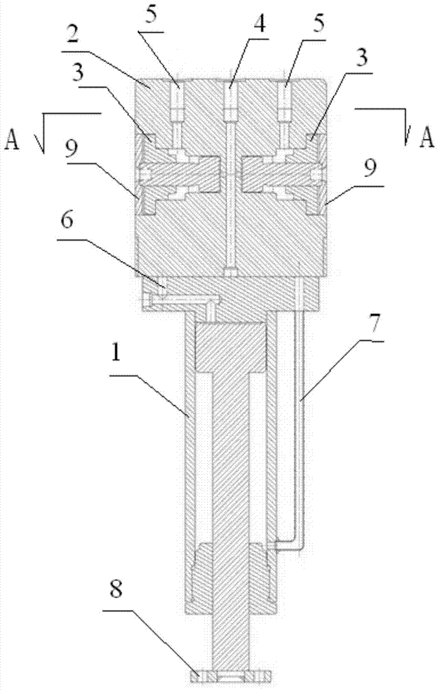
[0016] see figure 1 and figure 2 Shown:

[0017] The reaction force mechanism in the full hydraulic hole for the vibrator in the well provided by the present invention includes a reaction force cylinder 1 and a support device 2, wherein the reaction force cylinder 1 is connected to the lower part of the support device 2, and several support cylinders 3 are arranged in the support device 2 , several support oil cylinders 3 are connected with the first oil delivery pipe 4, each support oil cylinder 3 is connected with a first oil return pipe 5, several first oil return pipes 5 are connected, and the reaction force cylinder 1 is connected with a second oil delivery pipe 6, The reaction force cylinder 1 is also connected with a second oil return pipe 7, the first oil delivery pipe 4 and the first oil return pipe 5 are controlled by the support controller of the hydraulic console, and the second oil delivery pipe 6 and the second oil return pipe 7 are controlled by the reaction f...


PUM


Abstract

The invention discloses a well controllable epicentre hydraulic hole counterforce mechanism, comprising a counterforce oil cylinder and a support device, wherein the counterforce oil cylinder is in connection with the lower part of the support device; the support device is internally provided with a plurality of support oil cylinders which are all in communication with a first petroleum pipeline; each support oil cylinder is in connection with a first oil return pipe; the plurality of support oil cylinders are in communication; the counterforce oil cylinder is in communication with a second petroleum pipeline, and a second oil return pipe; the first petroleum pipeline and the first oil return pipe are controlled by the support controller of a hydraulic console; the second petroleum pipeline and the second oil return pipe are controlled by the counterforce controller of the hydraulic console. The well controllable epicentre hydraulic hole counterforce mechanism greatly reduces peripheral equipment weights and sizes, allows the popularization of a controllable epicentre in mountainous region exploration to be possible, solves the problem of larger size of a set of equipment when a present controllable epicentre provides counterforce through deadweight, and effectively mitigates system complexity.

Description

technical field [0001] The invention relates to an in-hole reaction force mechanism, in particular to a fully hydraulic in-hole reaction force mechanism for a vibrator in a well. Background technique [0002] At present, the vibrator is an important part of the seismic exploration system. The vibrator is a non-explosive source that is widely used. Since the traditional large-scale vibrator uses its own weight to provide the shock reaction force, most of them are vehicle-mounted vibrators. Its volume is large, and large machinery and equipment cannot go up to carry out operations when exploring in mountainous areas. Based on the disadvantages of traditional vibrators, placing the vibrator excitation mechanism in the hole and using the hole wall to provide reaction force is the solution to this problem. How to use the hole wall to provide counter force is the key technical issue that restricts the successful application of seismic control in wells. A reaction force system of ...

Claims


Application Information

Patent Timeline
Patent Type & Authority Patents(China)
IPC IPC(8): G01V1/133
CPCG01V1/133
Inventor 杜立志张晓培张琪牛建军翟松涛邱建慧张汝凯吕守航
Owner JILIN UNIV
Learn More