
On screen display data electromagnetic compatible test system and method

An electromagnetic compatibility and test system technology, applied in the direction of measuring electricity, measuring devices, measuring electrical variables, etc., can solve the problems of inability to record test results, time difference between monitoring video and test data, etc.

Active Publication Date: 2016-04-06
GUANGZHOU CHANGEN ELECTRONICS TECH CO LTD
View PDF8 Cites 10 Cited by
  • Summary
  • Abstract
  • Description
  • Claims
  • Application Information

AI Technical Summary

Problems solved by technology

In this way, there will be a time difference between the surveillance video and the test data, and accurate test results cannot be recorded.

Method used

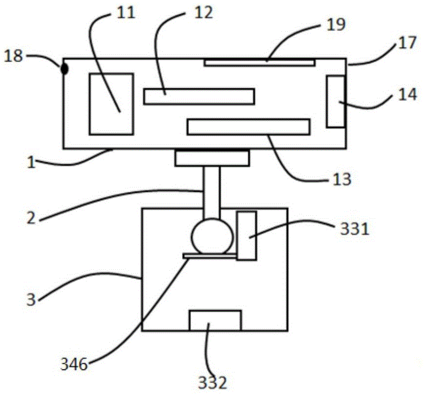
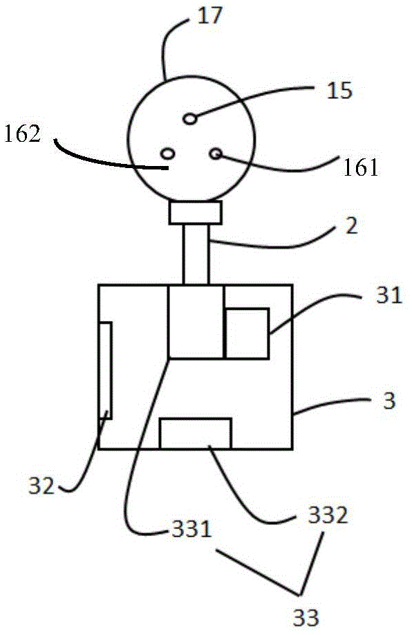

Image

  • On screen display data electromagnetic compatible test system and method
  • On screen display data electromagnetic compatible test system and method
  • On screen display data electromagnetic compatible test system and method

Examples


Embodiment 1

[0075] Embodiment 1 An electromagnetic compatibility test system that displays data on the screen

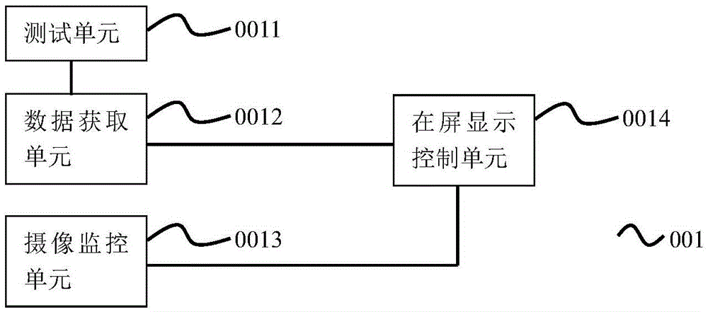
[0076] figure 1 A schematic structural diagram of an electromagnetic compatibility test system 001 for displaying data on a screen provided by an embodiment of the present invention.

[0077] Such as figure 1As shown, the present invention provides a kind of electromagnetic compatibility test system 001 of displaying data on the screen; Comprising: test unit 0011, the data acquisition unit 0012 that links to each other with test unit 0011, camera monitor unit 0013, and described camera monitor unit respectively 0013 and the on-screen display control unit 0014 connected to the data acquisition unit 0012, wherein,

[0078] The test unit 0011 is used to test the device under test and generate first test data;

[0079] The data acquisition unit 0012 is used to obtain the first test data generated by the test unit 0011, and to extract the target data in the first test data, and ge...

Embodiment 2

[0125] Embodiment 2 An electromagnetic compatibility test method for displaying data on the screen

[0126] Figure 8 It is a schematic flowchart of an electromagnetic compatibility testing method for displaying data on a screen provided by an embodiment of the present invention.

[0127] Such as Figure 8 As shown, the present invention provides a kind of electromagnetic compatibility testing method of displaying data on the screen, comprising:

[0128] The test unit 0011 tests the device under test and generates first test data;

[0129] The data acquisition unit 0012 acquires the first test data generated by the test unit 0011, and extracts the target data in the first test data, and then generates the second test data according to the obtained target data, and sends the obtained second test data to the on-screen display control unit 0014;

[0130] The camera monitoring unit 0013 performs video monitoring of the area to be tested, and generates video data, and sends the...


PUM


Abstract

The invention provides an on screen display data electromagnetic compatible test system and method. The system comprises a test unit, a data acquisition unit, a shooting monitoring unit, and an on screen control unit, wherein the data acquisition unit is used for obtaining first test data generated by the test unit, extracting the target data in the first test data to generate second test data, and sending the second test data to the on screen control unit; the shooting monitoring unit is used for performing video monitoring on the area to be tested, and sending obtained video data to the on screen control unit; the on screen control unit is used for displaying received second test data and video data on a same screen. The on screen display data electromagnetic compatible test system can realize simultaneous display of test data and monitoring videos, and provide great convenience for test personnel.

Description

technical field [0001] The invention relates to the field of electromagnetic interference, in particular to an electromagnetic compatibility testing system and method for displaying data on a screen. Background technique [0002] In the place where the electromagnetic compatibility test is carried out, on the one hand, the monitoring camera monitors the area to be tested and the sample to be tested in real time, and on the other hand, the electromagnetic compatibility test equipment tests the sample to be tested and generates test data or test reports; common, The test report cannot be displayed in the surveillance video in real time. The monitoring personnel need to watch the surveillance video on the one hand, and then record the test data in the test software when an abnormality is found; or observe the surveillance video when seeing the abnormal data. In this way, there will be a time difference between the monitoring video and the test data, and accurate detection resu...

Claims


Application Information

Patent Timeline
IPC IPC(8): G01R31/00
CPCG01R31/001G01R1/025
Inventor 李楠李军
Owner GUANGZHOU CHANGEN ELECTRONICS TECH CO LTD
Learn More