
Gravity balance difference pumping unit

A technology of gravity balance and pumping unit, which is applied in the direction of brake actuators, production fluids, boreholes/well components, etc., can solve the problems of unsatisfactory energy saving effects, and achieve safe and reliable parameter adjustment operations, low energy consumption, and reduced The effect of power

Active Publication Date: 2016-04-06
靳宝才
View PDF12 Cites 3 Cited by
  • Summary
  • Abstract
  • Description
  • Claims
  • Application Information

AI Technical Summary

Problems solved by technology

[0003] The technical problem to be solved by the present invention is to provide a pumping unit with poor gravity balance in view of the unsatisfactory energy-saving effect mentioned above. The machine adopts the gravity counterweight balance method to match the two ends to the minimum difference, and uses the moving pulley multiplier distance theory, that is, the remarkable effect of the labor-saving distance, and integrates the three excellent conditions into an innovative structure of mechanical and electrical integration, and the output power is large. Achieve long stroke and solve the technical problems of low mechanical efficiency and high energy consumption of conventional pumping units

Method used


Image

  • Gravity balance difference pumping unit
  • Gravity balance difference pumping unit
  • Gravity balance difference pumping unit

Examples


Embodiment Construction

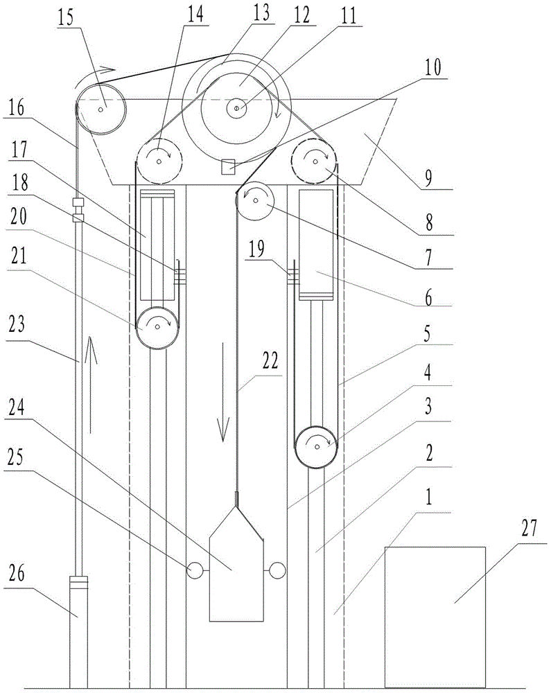
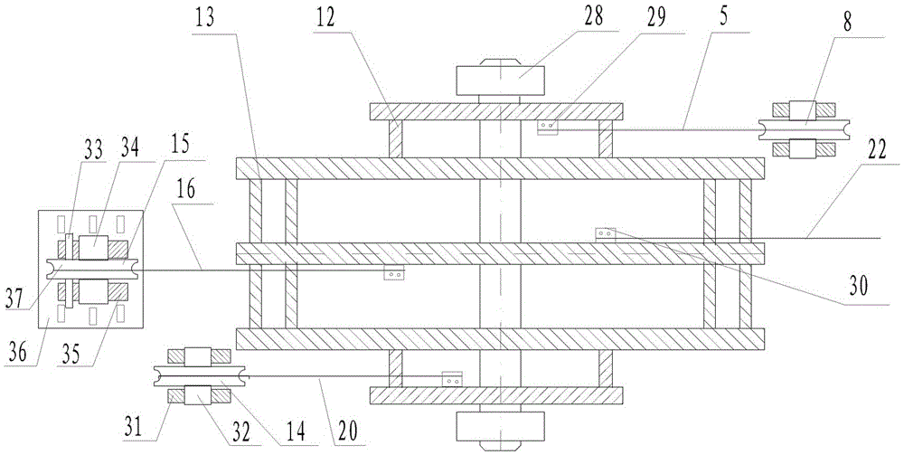
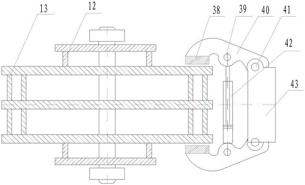
[0038]Pumping unit with poor gravity balance, including frame 1, upper platform 9 fixed on the top of the frame, first driving cylinder 6, second driving cylinder 17, gravity combination drum, driving cylinder pull rope, counterweight pull rope, and sucker rod 23 , counterweight iron 24, hydraulic braking device 10, hydraulic pump station 27. The first driving cylinder 6 and the second driving cylinder 17 are respectively installed on the front and rear sides of the frame 1, the first driving cylinder 6 and the second driving cylinder 17 are connected to the plunger pump of the hydraulic pump station 27 through the oil circuit, the first The piston rod of the drive cylinder 6 is connected with the first movable pulley 4, and the piston rod of the second drive cylinder 17 is connected with the second movable pulley 21. The first movable pulley 4 and the second movable pulley 21 are connected to the front and rear sides of the frame 1 respectively. On the movable pulley slideway...


PUM


Abstract

The invention provides a gravity balance difference pumping unit which comprises a frame, an upper platform fixed to the top end of the frame, a first drive oil cylinder, a second drive oil cylinder, gravity combination rollers, a drive oil cylinder pull rope, a balance weight pull rope, a pumping rod, balance weight iron and a hydraulic pump station. The first drive oil cylinder and the second drive oil cylinder are mounted on the front side and the rear side of the frame respectively, a piston rod of the first drive oil cylinder and a piston rod of the second drive oil cylinder are connected with a first movable pulley and a second movable pulley respectively, and the first movable pulley and the second movable pulley can slide up and down on a movable pulley slideway of the frame. The upper platform is connected with a supporting wheel and a front bearing gravity wheel. The drive oil cylinder pull rope is wound around the movable pulleys, the supporting wheel and the front bearing gravity wheel and fixedly connected to the gravity combination drive rollers. One end of the balance weight pull rope is connected with the balance weight iron, and the other end of the balance weight pull rope is wound around the supporting wheel and fixedly connected to the gravity combination rollers and connected with the pumping rod; under the action of the gravity combination rollers, the balance weight iron slides up and down along the slideway of the frame through the rollers on the two sides. According to the gravity balance difference pumping unit, output power is larger, a long stroke is reached, and the technical problems that a conventional pumping unit is low in efficiency and high in energy consumption.

Description

technical field [0001] The invention relates to an oil field extraction machine, in particular to an oil pumping unit with poor gravity balance. Background technique [0002] The pumping unit is the main equipment for oil exploitation. The heavy beam pumping unit has been used for oil production. This kind of pumping unit consumes a lot of energy, has low efficiency, high failure rate, and large shutdown loss. The auxiliary cooperation of the crane makes the operation difficult and the power resources are seriously wasted. After several years of continuous exploration, innovation and transformation, and striving for energy-saving effects, they have not escaped from the structural principles. Although the investment is large, the energy-saving effects are not satisfactory. Currently, about 20% to 30% of them are still operating in the In high energy consumption state. Contents of the invention [0003] The technical problem to be solved by the present invention is to prov...

Claims


Application Information

Patent Timeline
IPC IPC(8): E21B43/00F16D65/14
CPCE21B43/121F16D65/14
Inventor 靳宝才靳凯赵楠剑
Owner 靳宝才
Learn More