
Sand mixer

A sand mixer and sand mixing technology, which is used in the cleaning/processing machinery of casting materials, casting molding equipment, metal processing equipment, etc., can solve the problems of high installed power and high energy consumption

Inactive Publication Date: 2016-04-06
永红保定铸造机械有限公司
View PDF5 Cites 8 Cited by
  • Summary
  • Abstract
  • Description
  • Claims
  • Application Information

AI Technical Summary

Problems solved by technology

[0002] At present, the sand mixing method of the clay sand mixer is a fixed chassis, that is, the sand scraper rotates along the center of the sand mixing cylinder to scrape up the mixture and mix the mixture evenly with the high-speed rotor fixed on the upper part of the cylinder wall. After the molding sand is mixed, it is qualified. The molding sand is unloaded by the discharge door on the wall of the barrel to complete the mixing of molding sand; the sand mixer with this structure needs to scrape the entire mixture by scraping the sand during sand mixing, so there is an installed power Disadvantages of large size and high energy consumption

Method used


Image

  • Sand mixer
  • Sand mixer

Examples


Embodiment Construction

[0017] The present invention will be further described in detail below in conjunction with the accompanying drawings and specific embodiments.

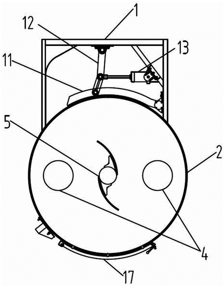
[0018] Depend on Figure 1-2 As can be seen from the illustrated embodiment, the present embodiment includes a sand mixer support frame 1, on which a sand mixing chamber is provided, and the sand mixing chamber includes a sand mixing cylinder 2 vertically fixed on the support frame 1, and the sand mixing chamber is vertically fixed on the support frame 1. The bottom of the cylinder 2 is horizontally equipped with a rotating chassis 3, and the rotating chassis 3 is provided with a driving device that can make it rotate. The sand mixing cylinder 2 is closely matched with the rotating chassis 3, and also includes one, two or more blade rotors 4 for stirring , the rotating shaft of the vane rotor 4 extends vertically downward into the sand mixing chamber, the upper end of the rotating shaft of the vane rotor 4 is connected to the support ...


PUM


Abstract

The invention discloses a sand mixer which comprises a sand mixer supporting frame. A sand mixing chamber is arranged on the supporting frame and comprises a sand mixing barrel vertically fixed to the supporting frame. A rotary bottom disc is horizontally arranged at the bottom of the sand mixing barrel and provided with a drive device capable of driving the rotary bottom disc to rotate. The sand mixing barrel and the rotary bottom disc are in interference fit. The sand mixer further comprises one or two or more blade rotors with the stirring function. Rotating shafts of the blade rotors vertically downwards stretch into the sand mixing chamber. The upper ends of the rotating shafts of the blade rotors are rotationally connected with the supporting frame. The rotating shafts of the blade rotors are provided with rotating drive devices. The sand mixer further comprises a scraper. A scraper shaft of the scraper vertically downwards stretches into the sand mixing chamber along the axis of the rotary bottom disc. The upper end of the scraper shaft is fixedly connected with the supporting frame. A feeding hopper and a water spraying device are arranged above the sand mixing barrel. The sand mixing barrel is provided with a discharging door structure. The sand mixer has the beneficial effects that no dead corners exist during rotating sand mixing, the sand mixing quality is good, the installed power is small, and energy consumption is low.

Description

technical field [0001] The invention relates to a sand mixer. Background technique [0002] At present, the sand mixing method of the clay sand mixer is a fixed chassis, that is, the sand scraper rotates along the center of the sand mixing cylinder to scrape up the mixture and mix the mixture evenly with the high-speed rotor fixed on the upper part of the cylinder wall. After the molding sand is mixed, it is qualified. The molding sand is unloaded by the discharge door on the wall of the barrel to complete the mixing of molding sand; the sand mixer with this structure needs to scrape the entire mixture by scraping the sand during sand mixing, so there is an installed power Disadvantages of large size and high energy consumption. Contents of the invention [0003] The technical problem to be solved by the present invention is to provide a sand mixer, which has the characteristics of no dead angle during rotating sand mixing, good sand mixing quality, small installed power,...

Claims


Application Information

Patent Timeline
IPC IPC(8): B22C5/04
CPCB22C5/045
Inventor 李彦青付长娟李大鹏
Owner 永红保定铸造机械有限公司
Learn More