Multi permanent magnet high speed two-way electromagnet

A high-speed electromagnet and electromagnet technology, applied in the field of electromagnets, can solve the problems of increased eddy current loss, magnetic flux leakage of electromagnets, high operating frequency of electromagnets, etc., to increase the attraction area, increase electromagnetic force, and magnetic induction intensity evenly distributed effect

Active Publication Date: 2017-05-24
无锡格迪斯机械制造有限公司
View PDF5 Cites 0 Cited by
  • Summary
  • Abstract
  • Description
  • Claims
  • Application Information

AI Technical Summary

Problems solved by technology

[0003] Conventional E-type electromagnets have a high operating frequency. Due to repeated magnetization, the eddy current loss increases and the heat production increases, which affects the magnetic permeability of magnetic materials and reduces the stability and reliability of the electromagnet.
Moreover, conventional electromagnets are prone to magnetic flux leakage, which will adversely affect the performance of the electromagnet.

Method used


Image

  • Multi permanent magnet high speed two-way electromagnet
  • Multi permanent magnet high speed two-way electromagnet
  • Multi permanent magnet high speed two-way electromagnet

Examples


Embodiment Construction

[0027] The present invention will be described in more detail below with examples in conjunction with the accompanying drawings.

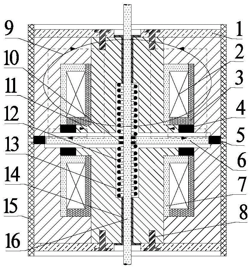
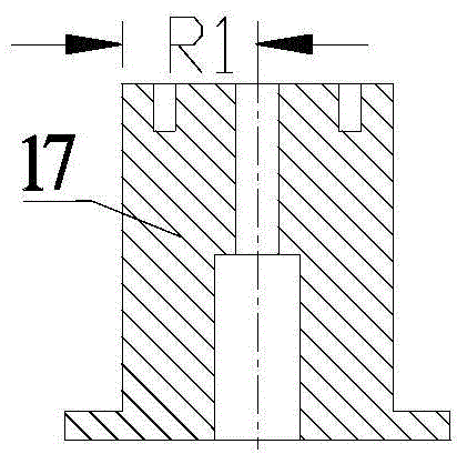
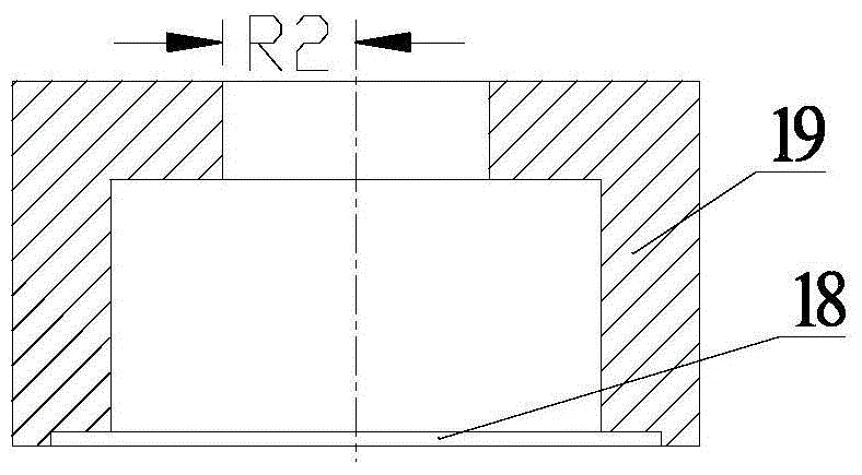
[0028] to combine figure 1 , Fig. 2, Fig. 3, the composition of the first embodiment of the multi-permanent double-day type high-speed bidirectional electromagnet of the present invention includes an outer shell 15, a Japanese-type iron core 9, a coil 2, an armature 6, a snap ring 10, and a bobbin 7. Sealing resin 3, embedded valve sleeve 14, return spring 13 and valve stem 16. The outer casing 15 is a center with a through hole, and the corresponding position of the large permanent magnet is also a cylinder with a through hole 26, and the upper and lower ends are respectively provided with a fixed nut 1. Japanese type iron core 9 is made up of main magnetic pole 17, auxiliary magnetic pole 19 and small permanent magnet 4, and main magnetic pole 17 is the cylinder structure that has stepped through hole in the center, and its upper end face is axi...


PUM


Abstract

The invention provides a multi-permanent magnet high-speed two-way electromagnet. Each permanent magnet high-speed electromagnet comprises an iron core, a coil, an outer shell, an annular small permanent magnet and a large permanent magnet, wherein each iron core comprises a cylindrical primary magnetic pole and a circular secondary magnetic pole; each coil is arranged in a coil mounting groove; each outer shell sleeves the outside of each iron core; an annular flange extends out of the bottom of each primary magnetic pole or each secondary magnetic pole; the small permanent magnet is inlaid between each annular flange and each primary magnetic pole or each secondary magnetic pole; each small permanent magnet is in radial radiation magnetization; two permanent magnet high-speed electromagnets are symmetrically arranged; an armature and a valve rod are shared by the two permanent magnet high-speed electromagnets; a through hole is formed in the middle of each primary magnetic pole; the valve rod is arranged in each through hole in a penetrating manner; the armature is fixed on the valve rod; each large permanent magnet is a cylindrical ring which is concentric with each iron core and is inlaid between two pairs of magnetic poles arranged up and down; and each large permanent magnet is in radial radiation magnetization. The multi-permanent magnet high-speed two-way electromagnet is fast in response, high in stability, low in leakage flux and applicable to an electronic-controlled fuel system of a diesel engine, and can be in two-way motion.

Description

technical field [0001] The invention relates to an electromagnet, in particular to a high-speed electromagnet for an electronically controlled fuel system of a diesel engine. Background technique [0002] Electronically controlled fuel injection system is the development direction of modern diesel engine fuel system. An electromagnet whose response speed can reach milliseconds can be called a high-speed electromagnet. At this stage, whether it is a time control system or a pressure-time control high-pressure common rail system, high-speed electromagnets are important components to ensure the normal operation of the electronically controlled fuel system. Its strong electromagnetic force and fast response characteristics directly affect the fuel injection timing. and precise control of fuel injection volume. In order to meet the increasingly stringent emission regulations, improve fuel economy, and reduce harmful emissions, higher requirements are placed on the performance o...

Claims


Application Information

Patent Timeline
Patent Type & Authority Patents(China)
IPC IPC(8): H01F7/08H01F7/122F02M51/06
Inventor 范立云周伟费红姿马修真刘鹏
Owner 无锡格迪斯机械制造有限公司
Why Eureka
Try Eureka