Double permanent magnet high speed two-way electromagnet

A high-speed electromagnet and electromagnet technology, which is applied in the field of electromagnets, can solve problems such as the decrease in the reliability and life of solenoid valves, the decrease in the magnetic permeability of magnetic materials, and the increase in heat generation of coils, etc., to achieve uniform distribution of magnetic induction intensity and increase magnetic induction. The number of lines, the effect of increasing the electromagnetic force

Active Publication Date: 2017-08-04
HARBIN ENG UNIV
View PDF5 Cites 0 Cited by
  • Summary
  • Abstract
  • Description
  • Claims
  • Application Information

AI Technical Summary

Problems solved by technology

[0003] The commonly used traditional E-type electromagnet is generally driven by the Hold&Peak method. However, the high current increases the power consumption and heat production of the solenoid valve, and puts forward more stringent requirements for the working temperature of the coil and its sealing materials. At the same time Caused the reliability and life of the solenoid valve to decline
The pull-in phase of the armature is maintained by a small current, especially when working with a large pulse width, it will also increase the heat generation of the coil, resulting in a decrease in the magnetic permeability of the magnetic material

Method used


Image

  • Double permanent magnet high speed two-way electromagnet
  • Double permanent magnet high speed two-way electromagnet
  • Double permanent magnet high speed two-way electromagnet

Examples


Embodiment Construction

[0026] The present invention will be described in more detail below with examples in conjunction with the accompanying drawings.

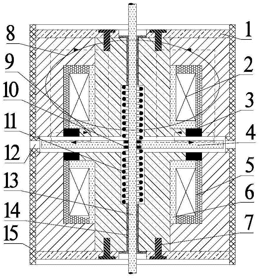
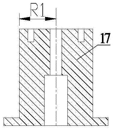
[0027] combine figure 1 , figure 2 , image 3 , Fig. 4 (a), Fig. 4 (b), Fig. 4 (c), the composition of double permanent magnet Japanese type high-speed two-way electromagnet first embodiment of the present invention comprises outer casing 15, Japanese type iron core 8, coil 2. Coil bobbin 6, sealing resin 5, return spring 11, embedded valve sleeve 14, armature 4 and valve stem 13. The Japanese-shaped iron core 8 is composed of the main magnetic pole 17, the auxiliary magnetic pole 16 and the permanent magnet 3, and the two groups are symmetrically distributed on both sides of the armature; the main magnetic pole 17 is a cylindrical structure with a stepped through hole in the center, and a belt The small hole of the screw thread, the auxiliary magnetic pole 16 is a cylinder with a stepped through hole, and the radius R1 of the main magnetic pol...


PUM


Abstract

The invention provides a high-speed bidirectional electromagnet with double permanent magnets. It includes two permanent magnet high-speed electromagnets. Each permanent magnet high-speed electromagnet includes an iron core, a coil and an outer shell. The iron core is composed of a cylindrical main magnetic pole and a circular auxiliary magnetic pole. A coil is installed between the main magnetic pole and the auxiliary magnetic pole. The coil is installed in the coil installation groove, the outer casing is set outside the iron core, and the main magnetic pole or the auxiliary magnetic pole extends from the bottom of the annular flange, and also includes an annular permanent magnet, which is embedded in the annular flange and the main magnetic pole or auxiliary magnetic pole. In the middle of the magnetic poles, the magnetization direction of the permanent magnet is radial radiation magnetization. Two permanent magnet high-speed electromagnets are symmetrically arranged and the permanent magnet ends are opposite. The two permanent magnet high-speed electromagnets share an armature and a valve stem. The middle of the main magnetic pole With a through hole, the valve stem passes through the through hole, and the armature is fixed on the valve stem. The double permanent magnet high-speed bidirectional electromagnet of the present invention has fast response speed, small drive current, bidirectional movement, long service life and high reliability, and is suitable for electronically controlled fuel oil systems of diesel engines.

Description

technical field [0001] The invention relates to an electromagnet, in particular to a high-speed electromagnet for an electronically controlled fuel system of a diesel engine. Background technique [0002] With the continuous development of diesel engine electronic control technology, electronically controlled fuel injection system has become an inevitable trend to meet the increasingly stringent diesel engine emission regulations. The electronically controlled fuel injection system is an effective means to improve the high fuel economy of diesel engines and reduce harmful emissions due to its characteristics of high injection pressure, fuel injection timing, and flexible and controllable fuel injection rules. An electromagnet whose response speed can reach milliseconds can be called a high-speed electromagnet. High-speed electromagnet is an important component of diesel engine electronic control unit and fuel injection device. Its fast response characteristic is the premise...

Claims


Application Information

Patent Timeline
Patent Type & Authority Patents(China)
IPC IPC(8): H01F7/16
Inventor 范立云周伟刘鹏费红姿李学民李文辉赵建辉
Owner HARBIN ENG UNIV
Why Eureka
Try Eureka