A kind of high-efficiency drilling tool for rock drilling machine

A rock drill and high-efficiency technology, applied in the field of high-efficiency rock drill drilling tools, can solve the problems of small vibration force of the drill bit, small destructive force of surrounding stones, low work efficiency, etc., and achieve the effect of improving work efficiency.

Inactive Publication Date: 2018-04-03
HUNAN UNIV OF ARTS & SCI
View PDF6 Cites 0 Cited by
  • Summary
  • Abstract
  • Description
  • Claims
  • Application Information

AI Technical Summary

Problems solved by technology

Classification Rock drills can be divided into four categories according to their power sources: pneumatic rock drills, internal combustion rock drills, electric rock drills and hydraulic rock drills. The drill tools used in rock drills are generally composed of drill rods and alloy steel drill bits. The drill rod is used to connect the drill bit and the rock drilling tool. The drill rods generally used in mine shaft engineering are hexagonal hollow steel and hollow round steel. 38mm, steel brazing includes finished steel brazing and forged steel brazing. The finished drill rod is forged according to a certain length and then directly installed on the drill bit to drill holes. Forged steel brazing is to cut hollow hexagonal steel according to needs, and then use The forging machine forges the drill tail and the drill head, and then installs the drill bit to drill the hole. The drill bit commonly used in mine shaft engineering is a straight alloy steel drill bit, and a cross-shaped alloy drill bit is also used when drilling into the hollow hole; Y-shaped alloy drill bit and X-shaped alloy drill bit, but the cost of the straight drill bit is relatively low. It can be reused after grinding. The size of the drill bit is generally 36mm---44mm. The traditional drill bit and drill rod are mostly screwed and fixedly connected. The vibration force of the drill bit is small during work, and the destructive force to the surrounding stone is small. The work efficiency is low, for this reason, we propose a kind of high-efficiency rock drilling machine drilling tool

Method used


Image

  • A kind of high-efficiency drilling tool for rock drilling machine
  • A kind of high-efficiency drilling tool for rock drilling machine
  • A kind of high-efficiency drilling tool for rock drilling machine

Examples


Embodiment Construction

[0017] The following will clearly and completely describe the technical solutions in the embodiments of the present invention with reference to the accompanying drawings in the embodiments of the present invention. Obviously, the described embodiments are only some, not all, embodiments of the present invention. Based on the embodiments of the present invention, all other embodiments obtained by persons of ordinary skill in the art without making creative efforts belong to the protection scope of the present invention.

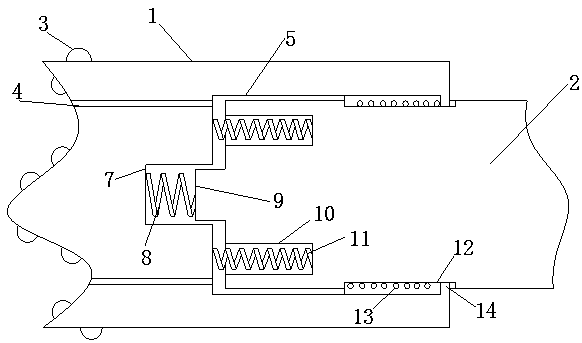
[0018] see Figure 1-2 , the present invention provides a technical solution: a high-efficiency rock drilling tool, including a drill bit 1 and a drill rod 2, the surface of the drill bit 1 is evenly provided with protrusions 3, and the protrusions 3 make the drill bit 1 work When the destructive power to the surrounding stone is enhanced, it helps to improve work efficiency. The surface of the drill bit 1 has a through hole 4, and the inner side of the throug...


PUM


Abstract

The invention discloses an efficient drill tool of a rock drill. The efficient drill tool comprises a drill head and a drill rod. The surface of the drill head is uniformly provided with protrusions. A groove is reserved in the back side of the drill head. The front end of the drill rod is inserted into an inner cavity of the groove. The drill rod is connected with the inner cavity of the groove through a vibrating mechanism. Two ends of a fourth spring are connected with a groove wall of the groove and the front end of the drill rod respectively. The front end of the drill rod is provided with a limit pipe chase. The groove bottom of the groove is provided with a limit rod corresponding to the limit pipe chase. Sliding grooves are formed in the upper side and the lower side of a rod wall of the drill rod. An inner cavity of each sliding groove is provided with sliding blocks. The outer sides of the sliding blocks are connected with a fifth spring. According to the drill tool, the drill head is connected with the drill rod through the vibrating mechanism to enable the drill head to generate large vibration during working through the impact force provided by a rock drill to cause strong damage to surrounding stones so as to improve working efficiency.

Description

technical field [0001] The invention relates to the technical field of rock drilling machines, in particular to a high-efficiency drilling tool for rock drilling machines. Background technique [0002] The rock drill works on the principle of impact crushing. When working, the piston makes high-frequency reciprocating motion and continuously impacts the drill tail. Under the action of the impact force, the sharp wedge-shaped drill bit crushes the rock and digs into a certain depth to form a dent. After the piston retreats, the drill bit After turning a certain angle, the piston moves forward, and when it hits the shank again, a new dent is formed. The fan-shaped rock block between the two dents is sheared by the horizontal component force generated by the drill bit. The piston continuously impacts the drill tail, and continuously inputs compressed air or pressure water from the center hole of the drill to discharge the rock slag out of the hole, that is, a circular drill h...

Claims


Application Information

Patent Timeline
Patent Type & Authority Patents(China)
IPC IPC(8): E21B1/30E21B10/36E21B17/00
CPCE21B1/00E21B10/36E21B17/00
Inventor 罗佑新文会军周宇
Owner HUNAN UNIV OF ARTS & SCI
Why Eureka
Try Eureka