
Blower

A technology of a hair dryer and a blowing pipe, which is used in road cleaning, construction, cleaning methods, etc., can solve problems such as the reduction of the working efficiency of the hair dryer, and achieve the effect of improving the blowing efficiency and good heat dissipation effect.

Active Publication Date: 2016-03-30
POSITEC POWER TOOLS (SUZHOU) CO LTD
View PDF11 Cites 9 Cited by
  • Summary
  • Abstract
  • Description
  • Claims
  • Application Information

AI Technical Summary

Problems solved by technology

But the resulting disadvantage is that the work efficiency of the whole hair dryer is reduced.

Method used


Image

  • Blower
  • Blower
  • Blower

Examples


Embodiment Construction

[0070] The preferred embodiments of the present invention will be described in detail below in conjunction with the accompanying drawings, so that the advantages and features of the present invention can be more easily understood by those skilled in the art, so as to define the protection scope of the present invention more clearly.

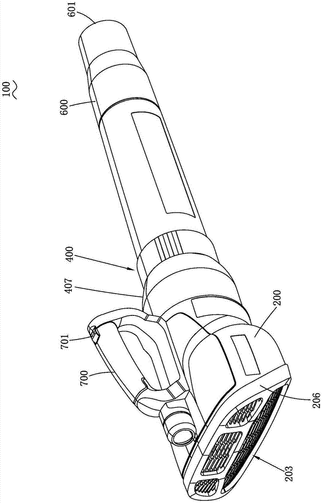
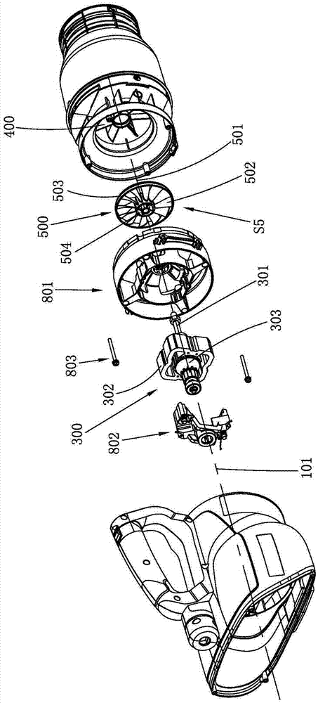
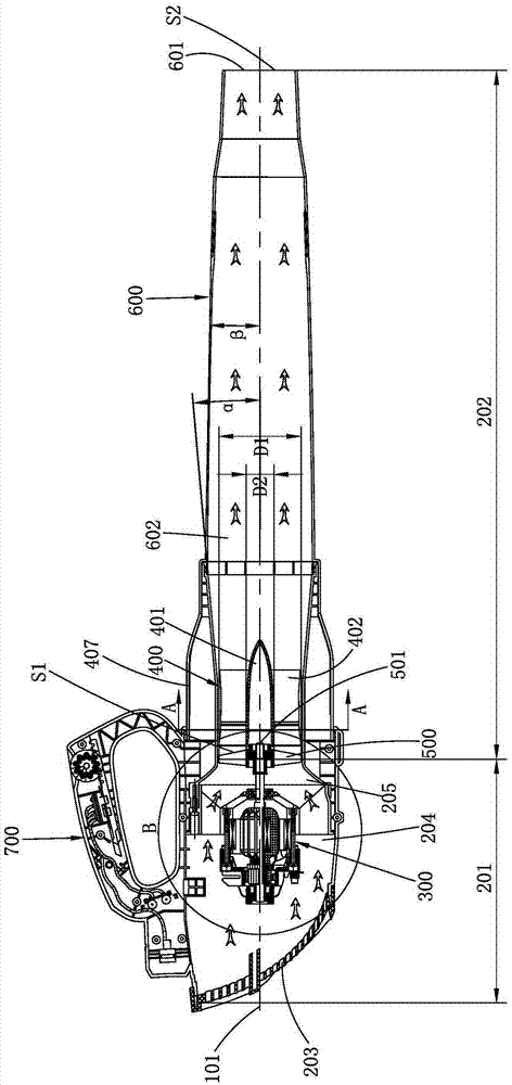
[0071] Figure 1 to Figure 7 Shown is a hair dryer 100 according to a first embodiment of the present invention. The hair dryer 100 includes a housing 200 , a motor 300 , a duct 400 , a fan 500 , and a blowing pipe 600 . Wherein, the motor 300 , the duct 400 and the fan 500 are all arranged in the casing 200 . The blowing pipe 600 is connected to the casing 200 . The air blowing pipe 600 is connected with the casing 200 to form an air flow channel 602 . The blowing pipe 600 is provided with an air outlet 601, and the air moves from the air passage 602 to the air outlet 601 and is blown out from the air outlet 601 for blowing away fallen leaves...


PUM


Abstract

The invention relates to a blower. The blower comprises a casing, a motor, an axial flow fan, a blowpipe and a duct, wherein a wind inlet is formed in the casing, and air enters the casing through the wind inlet; the motor is positioned in the casing; the axial flow fan is driven by the motor to rotate along a fan axis and generate air currents; the blowpipe is connected with the casing and is provided with a wind outlet, and the air currents are blown out of the wind outlet; the duct is used for guiding the air currents to move towards the wind outlet; air current passages are arranged in the casing and the blowpipe, and comprise an upstream region from the wind inlet to the axial flow fan and a downstream region from the axial flow fan to the wind outlet, the motor is arranged at the upstream region, and the duct is arranged at the downstream region.

Description

technical field [0001] The invention relates to an electric tool, especially a hair dryer. Background technique [0002] In daily life, a hair dryer is a relatively common tool, usually used to clean up grounds such as gardens or streets. [0003] For example, US Patent No. 4,880,364 discloses a hair dryer, which includes a housing, a motor, a fan, and an air duct. The fan rotates to generate airflow, which is blown out from the air duct. But what the fan of this kind hair dryer adopts is a centrifugal fan, and the air inlet is arranged below the centrifugal fan, and the air outlet is arranged at the side of the centrifugal fan. Due to the limitation of the structure of the centrifugal fan itself, the air volume blown out by this kind of hair dryer is often not large, so the blowing effect is not good, and the needs of users cannot be well met. [0004] Disclosed a kind of blower that adopts engine as power as U.S. Patent No. 5975862, engine utilizes gasoline as fuel as p...

Claims


Application Information

Patent Timeline
Patent Type & Authority Applications(China)
IPC IPC(8): E01H1/08
Inventor 霍立祥喻学锋宋康
Owner POSITEC POWER TOOLS (SUZHOU) CO LTD
Learn More