
Blanking detection equipment applied to metal workpieces

A technology for testing equipment and metal parts, applied in the field of blanking testing equipment, can solve the problems of high labor intensity, low production efficiency, and many equipment, and achieve the effects of improving product qualification rate, increasing work efficiency, and high degree of automation

Active Publication Date: 2016-03-30
南京大目信息科技有限公司
View PDF9 Cites 8 Cited by
  • Summary
  • Abstract
  • Description
  • Claims
  • Application Information

AI Technical Summary

Problems solved by technology

[0002] With the rapid development of the manufacturing industry, the production line is developing towards high speed, high quality, automation and flexibility, and traditional methods such as manual operation and manual feeding can no longer meet the needs
At present, the known metal parts are processed by machine tools. After the processing is completed, inspections are usually carried out to eliminate unqualified products. The whole process employs many people, labor intensity is high, and equipment is large. The safety factor of the equipment is not high, the power consumption is large, and the noise is large. , covers a large area, and the most important thing is that after manual operation, the product qualification rate is low, the production efficiency is also low, and the cost is greatly increased

Method used


Image

  • Blanking detection equipment applied to metal workpieces
  • Blanking detection equipment applied to metal workpieces
  • Blanking detection equipment applied to metal workpieces

Examples


Embodiment Construction

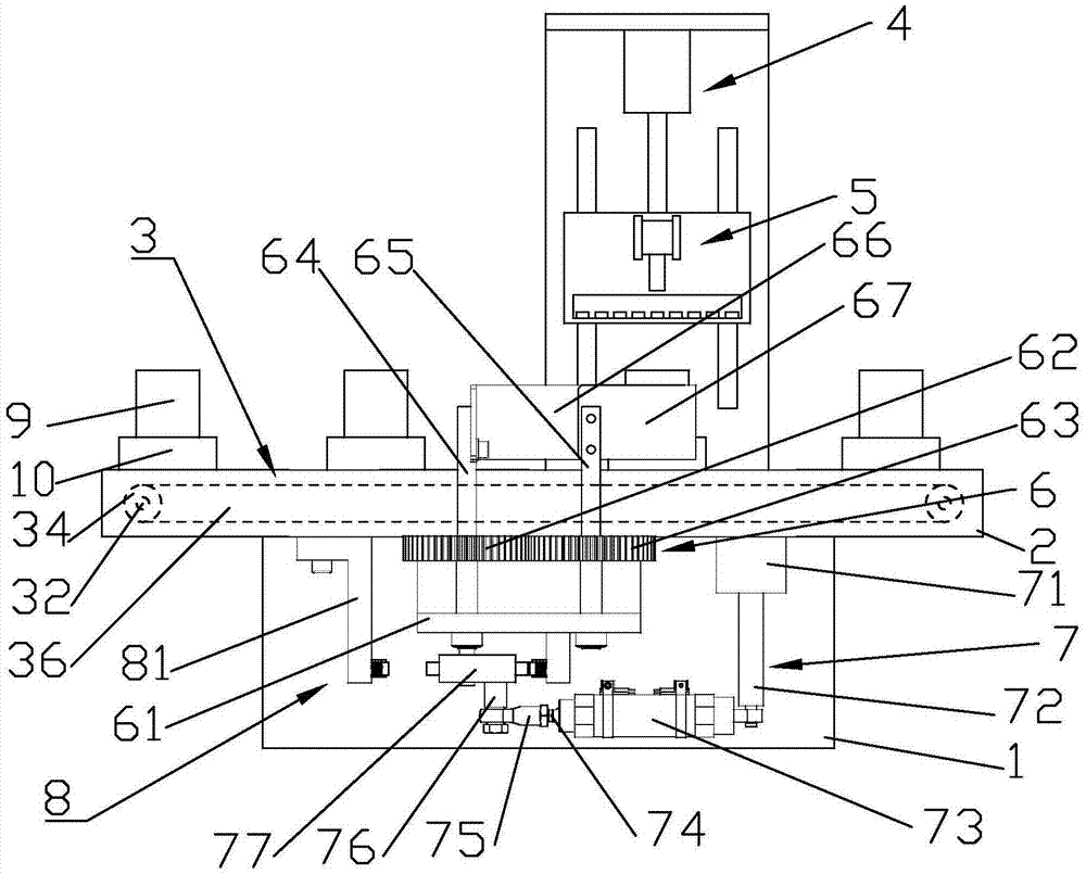
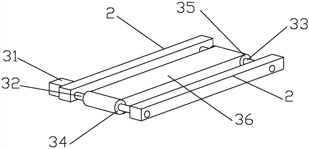
[0037] Such as Figure 1 to Figure 12 As shown, a blanking detection device applied to metal parts includes a frame 1 and a blanking platform 2, the blanking platform 2 is located on the frame 1, and a conveyor belt 36 is arranged between the blanking platforms 2, and the conveyor belt 36 A carrier 10 is arranged on the carrier 10, a metal piece 9 to be inspected is arranged on the carrier 10, and a conveyor belt 36 is connected with a feeding conveying device 3 . The inner side of the unloading platform 2 is provided with a detection device, the detection device includes a detection base plate 12, a detection stand 11, a camera assembly 5 and a lifting detection mechanism 4, the detection base plate 12 is installed on the unloading platform 2, and the detection base plate 12 is provided with a detection device. Stand 11, detection stand 11 is equipped with lifting detection mechanism 4, and lifting detection mechanism 4 is connected with camera assembly 5. The outside of the...


PUM


Abstract

The invention discloses blanking detection equipment applied to metal workpieces. The blanking detection equipment comprises a rack and a blanking platform, wherein the blanking platform is located on the rack; a conveyor belt is arranged in the blanking platform; a detection device is arranged on the inner side of the blanking platform; the detection device comprises a detection bottom plate, a detection vertical frame, a shooting component and a lifting detection mechanism; the detection bottom plate is arranged on the blanking platform; the detection vertical frame is arranged on the detection bottom plate; the detection vertical frame is provided with the lifting detection mechanism; the lifting detection mechanism is connected with the shooting component; a material baffling device is arranged on the outer side of the blanking platform; the material baffling device comprises a material baffling mechanism, a material baffling transmission mechanism and a material baffling positioning mechanism; the material baffling mechanism is arranged on the outer side of the blanking platform; the material baffling transmission mechanism is connected with the material baffling mechanism; the material baffling mechanism is located below the material baffling mechanism; and the material baffling positioning mechanism is arranged on the lower end of the blanking platform. The blanking detection equipment is simple in structure, high in pertinency and high in automation degree, and is scientific and convenient; and the blanking detection problem after the metal workpieces are machined is well solved.

Description

technical field [0001] The invention relates to a blanking detection device applied to metal parts. Background technique [0002] With the rapid development of the manufacturing industry, the production line is developing towards high speed, high quality, automation and flexibility, and traditional methods such as manual operation and manual feeding can no longer meet the needs. At present, the known metal parts are processed by machine tools. After the processing is completed, inspections are usually carried out to eliminate unqualified products. The whole process employs many people, labor intensity is high, and equipment is large. The safety factor of the equipment is not high, the power consumption is large, and the noise is large. , Covering a large area, and the most important thing is that after manual operation, the product qualification rate is low, the production efficiency is also low, and the cost is greatly increased. Contents of the invention [0003] The ob...

Claims


Application Information

Patent Timeline
IPC IPC(8): B65G47/22G01N21/89
CPCB65G47/22B65G2203/0208B65G2203/041B65G2205/04G01N21/89G01N2021/8908
Inventor 屠传伟
Owner 南京大目信息科技有限公司
Learn More