
a pair of coupled wheels

A technology for coupling wheel sets and wheel sets, which is applied to the fields of locomotive bogies, rail vehicles, passenger cars, urban rail vehicles, and EMUs, and can solve problems such as limited practicability, wheel rim rubbing, and lack of automatic centering capabilities , to achieve the effect of fast response and stable contact force value

Active Publication Date: 2017-07-21
ZHUZHOU ELECTRIC LOCOMOTIVE CO LTD
View PDF7 Cites 0 Cited by
  • Summary
  • Abstract
  • Description
  • Claims
  • Application Information

AI Technical Summary

Problems solved by technology

The biggest advantage of the rigid wheel set is that it is automatically guided, but the disadvantage is that there is a risk of snaking and the wear of the tread on the small curve line is large; the biggest advantage of the independent rotating wheel set is that the snaking stability is very good and the wheels can pass through the small curve. The disadvantage is the lack of automatic Alignment ability resulting in severe wheel rim rubbing
[0003] Most of the research on coupled wheelsets is based on magnetorheological technology. The structure of magnetorheological coupling technology is relatively complicated and its practicability is limited.

Method used


Image

  • a pair of coupled wheels
  • a pair of coupled wheels
  • a pair of coupled wheels

Examples


Embodiment Construction

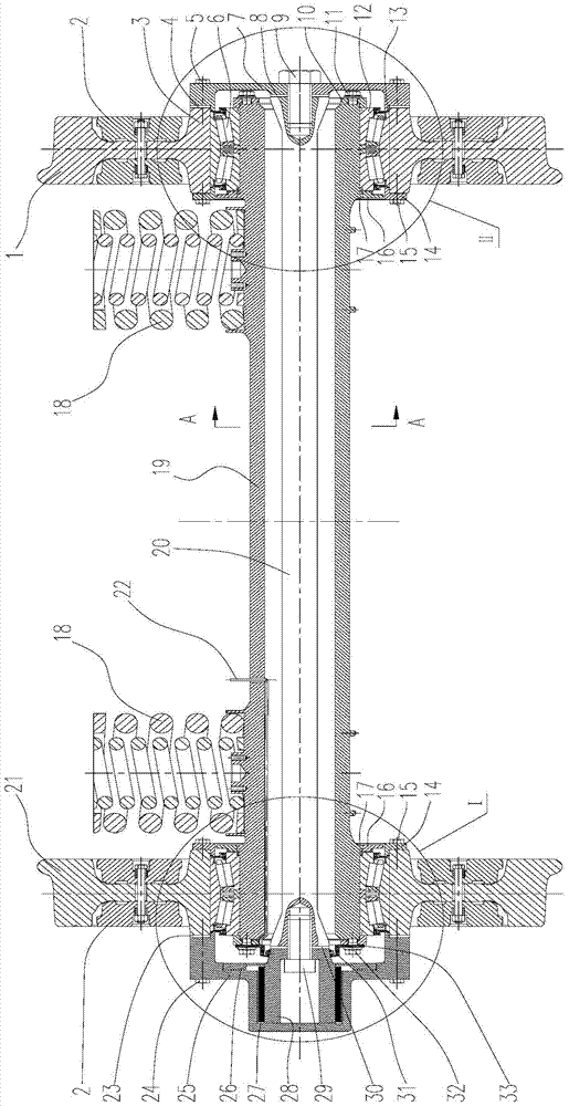
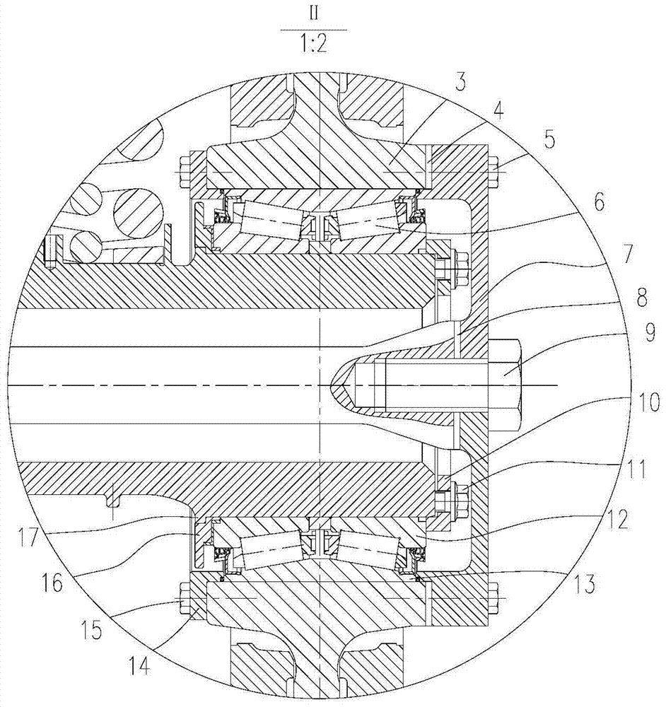
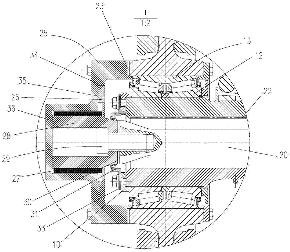
[0037] An electronically controlled coupling wheel set, such as figure 1 As shown in , for the convenience of description, the wheel set is divided into the rigid connection side according to the distribution position of the friction coupling mechanism ( figure 2 ) and the friction coupling side ( image 3 ).

[0038] For the rigidly connected side, the structure is as figure 1 and figure 2 shown. The hub 3 of the first wheel 1 cooperates with the outer ring 13 of the bearing 6 , and the outer ring 13 of the bearing 6 is pressed against both sides by the transmission disc 7 and the inner end cover 14 . The screw 5 is used for fastening the transmission disc 7 and the hub 3 , and the screw 15 is used for fastening the inner end cover 14 and the hub 3 . Therefore, the first wheel 1 forms an integral body with the outer ring 13 of the bearing 6, the transmission disc 7, and the inner end cover 14 when running. likefigure 1 and figure 2 As shown, the two ends of the shaf...


PUM


Abstract

The invention discloses an electric control coupling wheel pair. The electric control coupling wheel pair includes an axle; two end parts of the axle are respectively mounted in hub holes of a first wheel and a second wheel through corresponding bearings; the axle is a hollow pipe structure; a torsion rod is sleeved in the axle; the transverse force and the vertical force of the first wheel and the second wheel are transferred to the axle through the bearings; a transmission disc is mounted at the outer end of a hub of the first wheel; the inner end surface of the transmission disc is rigidly connected with one end part of the torsion rod; an outer end cover is arranged at the outer end of a hub of the second wheel; and a friction coupling mechanism is arranged between the hub and the outer end cover, and is used for enabling the wheel pair to form an independent rotating wheel pair or a torsion coupling wheel pair. The coupling wheel pair can exert the effects of automatic guidance and curve wear reduction to the greatest extent.

Description

technical field [0001] The invention relates to a coupling wheel set, which belongs to the field of rail vehicles, and is especially suitable for the bogie field of EMUs, passenger cars, urban rail vehicles and locomotives. Background technique [0002] The coupled wheel set is a wheel set structure between the rigid wheel set and the independent rotating wheel set. The torsional coupling stiffness of the left and right wheels is not as large as the rigid wheel set and does not seem to be zero like the independent rotating wheel set. The biggest advantage of the rigid wheel set is that it is automatically guided, but the disadvantage is that there is a risk of snaking and the wear of the tread on the small curve line is large; the biggest advantage of the independent rotating wheel set is that the snaking stability is very good and the wheels can pass through the small curve. The disadvantage is the lack of automatic The centering ability thus causes the rim to wear seriousl...

Claims


Application Information

Patent Timeline
Patent Type & Authority Patents(China)
IPC IPC(8): B60B37/06B60B35/12
CPCB60B35/122B60B37/06
Inventor 邓小星陈喜红陈国胜李冠军陈清明陶功安曾艳梅张建全
Owner ZHUZHOU ELECTRIC LOCOMOTIVE CO LTD
Learn More