Collar chamfering machine

A chamfering machine and collar technology, applied in the field of chamfering machines, can solve problems such as difficult control of chamfering width, slow chamfering speed, and easy deviation of chamfering angle, and achieve controllable chamfering width, fast chamfering speed, convenient effect

Active Publication Date: 2018-03-23
QIANJIANG SPRING HANGZHOU CO LTD
View PDF6 Cites 0 Cited by
  • Summary
  • Abstract
  • Description
  • Claims
  • Application Information

AI Technical Summary

Problems solved by technology

[0003] In order to overcome the problems in the prior art that the chamfering angle is easy to deviate, the chamfering width is difficult to control, and the chamfering speed is slow, the present invention provides a collar chamfering machine that is easy to control the chamfering angle and width and has a fast chamfering speed

Method used


Image

  • Collar chamfering machine
  • Collar chamfering machine
  • Collar chamfering machine

Examples


Embodiment Construction

[0019] The technical solutions of the present invention will be clearly and completely described below through specific embodiments in conjunction with the accompanying drawings.

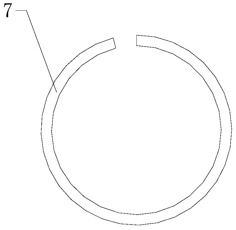
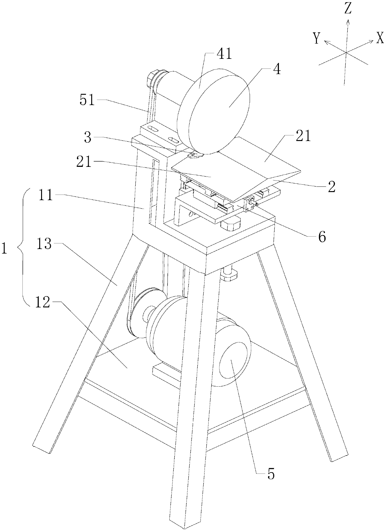
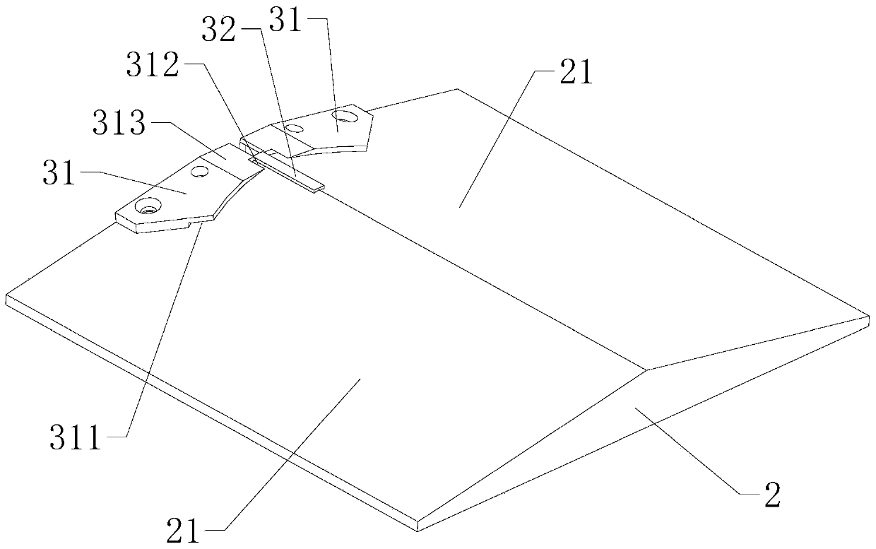
[0020] Please refer to Figure 1-4 As shown, the present invention provides a collar chamfering machine, including: a base 1 , a workbench 2 , at least one fixing piece 3 , a chamfering wheel 4 and a control motor 5 . The workbench 2 is arranged on the base 1, and the workbench 2 includes at least one work surface 21, and the work surface 21 is an inclined surface. The fixing member 3 is disposed on the working surface 21 . The fixing part 3 includes a clamping part 31 and a stopper 32 , the stopper 32 is disposed on the edge of the working surface 21 , and the clamping part 31 is disposed on one side of the stopper 32 . The clip 31 is provided with a downward-facing slot 311 , and the clip 31 is provided with a notch 312 at one end of the slot 311 , and the notch 312 is provided on one side of th...


PUM


Abstract

The invention provides a retainer ring chamfering machine. The retainer ring chamfering machine comprises a pedestal, a workbench, at least one fixed part, a chamfering wheel and a control motor, wherein the workbench is arranged on the pedestal; the workbench comprises at least one working surface which is an inclined plane; the at least one fixed part is arranged on the working surface; the fixed part comprises a clamping part and a blocking part which is arranged on the side edge of the working surface; the clamping part is arranged at one side of the blocking part; the clamping part is provided with a downward clamping slot; one end, at the clamping slot, of the clamping part is provided with a notch; the notch is arranged at one side of the blocking part; the chamfering wheel can be rotatably arranged above the workbench; the peripheral surface of the chamfering wheel is a friction surface made of a friction material; and the control motor is connected to the chamfering wheel to control the rotation of the chamfering wheel. According to the retainer ring chamfering machine provided by the invention, a retainer ring is positioned by virtue of the clamping part and the blocking part, and the retainer ring moves in a chamfering process, so that a chamfering angle has no deviation, and a chamfering width is controllable; and the motor drives the chamfering wheel to carry out chamfering, so that the chamfering speed is high, the working efficiency is high and the processing is convenient.

Description

technical field [0001] The invention relates to the technical field of chamfering machines, and in particular to a collar chamfering machine. Background technique [0002] The collar is mainly used to position the parts and act as an axial stop. Please refer to figure 1 As shown, it is a structural schematic diagram of a collar. In some usage environments, the two ends of the collar 7 need to be chamfered. However, in the prior art, people need to directly hold the collar 7 to make The end of collar 7 is close to the rotating grinding disc, and the grinding disc wears the end of collar 7 for chamfering, which is prone to chamfering angle deviation, chamfering width is difficult to control, and chamfering speed is slow. Contents of the invention [0003] In order to overcome the problems in the prior art that the chamfering angle is easy to deviate, the chamfering width is difficult to control, and the chamfering speed is slow, the invention provides a collar chamfering m...

Claims


Application Information

Patent Timeline
Patent Type & Authority Patents(China)
IPC IPC(8): B24B9/00B24B41/06B24B41/02
CPCB24B9/00B24B41/02B24B41/06
Inventor 张涌森杨国红张桂军宋福章
Owner QIANJIANG SPRING HANGZHOU CO LTD
Why Eureka
Try Eureka