Guide structure for blanking die

A technology of guiding structure and blanking die, which is applied in the direction of metal processing equipment, forming tools, manufacturing tools, etc., can solve the problems of poor stability of the guiding structure, achieve the effect of stable guiding, uniform radial force, and avoid easy wear

Inactive Publication Date: 2016-03-30
CHONGQING WANSI METAL SPECIAL TYPE FORMING
View PDF0 Cites 0 Cited by
  • Summary
  • Abstract
  • Description
  • Claims
  • Application Information

AI Technical Summary

Problems solved by technology

The main structure of the blanking die includes an upper die base, an upper die set under the upper die base, a lower die base, a lower die set on the upper part of the lower die base, and a material guide plate arranged on the upper part of the lower die base and located on both sides of the lower die base. The height of the material guide plate is higher than that of the lower die, and the lower part of the upper punch is usually made into a boss matching the blank blanking shape, and the size of the boss is basically the same as that of the die. In order to make the upper die seat drive The movement of the upper punch is stable. Usually, a guide post is set at the lower part of the mold base, and a guide hole is opened on the lower mold base. The guide post and the guide hole are guided through the sliding fit, but the above-mentioned guide structure has poor guiding stability.

Method used


Image

  • Guide structure for blanking die
  • Guide structure for blanking die

Examples


Embodiment Construction

[0012] The present invention will be described in further detail below by means of specific embodiments:

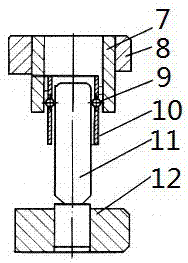
[0013] The reference signs in the accompanying drawings of the description include: blanking punch 1, first fixing plate 2, side edge 3, punching punch 4, material guide plate 5, second fixing plate 6, guide sleeve 7, upper die seat 8. Ball 9, cage 10, guide post 11, lower mold seat 12.

[0014] as attached figure 1 Shown: this embodiment is used for the guiding structure of punching die, comprises the vertical guide sleeve 7 that is arranged on the lower part of the upper die base 8 and the vertical guide post 11 that is arranged on the upper part of the lower die base 12, the diameter of the guide sleeve 7 Greater than the diameter of the guide post 11, the upper part of the guide post 11 is penetrated into the guide sleeve 7, and evenly arranged balls 9 are arranged between the guide post 11 and the inner wall of the guide sleeve 7, and are specifically fixed on the i...


PUM


Abstract

The invention discloses a guide structure for a blanking die. The guide structure for the blanking die is stable in guidance and comprises a vertical guide sleeve arranged at the lower portion of an upper die holder and a vertical guide column arranged at the upper portion of a lower die holder. The diameter of the guide sleeve is larger than that of the guide column. The upper portion of the guide column penetrates into the guide sleeve. An annular holding frame is arranged on the inner wall of the guide sleeve and provided with multiple balls. The balls are obliquely arranged in parallel at equal intervals.

Description

technical field [0001] The invention relates to a guide structure for a blanking die. Background technique [0002] Blanking is a stamping method that separates parts or blanks of required shape and size from sheet metal. The main equipment used is the punching die. The main structure of the blanking die includes an upper die base, an upper die set under the upper die base, a lower die base, a lower die set on the upper part of the lower die base, and a material guide plate arranged on the upper part of the lower die base and located on both sides of the lower die base. The height of the material guide plate is higher than that of the lower die, and the lower part of the upper punch is usually made into a boss matching the blank blanking shape, and the size of the boss is basically the same as that of the die. In order to make the upper die seat drive The movement of the upper punch is stable. Usually, a guide post is provided at the lower part of the mold base, and a guid...

Claims


Application Information

Patent Timeline
IPC IPC(8): B21D37/12B21D28/14
CPCB21D37/12B21D28/14
Inventor 谷毅
Owner CHONGQING WANSI METAL SPECIAL TYPE FORMING
Why Eureka
Try Eureka