
A ball grid array structure chip blanking equipment

A structure chip and ball grid array technology, applied in the field of ball grid array structure chip blanking equipment, can solve the problems of solder ball damage, increased product defect rate, low output, etc., so as to reduce the risk of damage and improve product yield. , the effect of improving production efficiency

Active Publication Date: 2018-03-27
江苏弘琪工业自动化有限公司
View PDF8 Cites 0 Cited by
  • Summary
  • Abstract
  • Description
  • Claims
  • Application Information

AI Technical Summary

Problems solved by technology

Manual rework and simple rework devices can only rework a small number of chips, with low efficiency and low output
Although the cost of the chip rework and ball planting machine is relatively expensive, its high-efficiency productivity has greatly reduced the price of BGA chips
At present, it is not only inefficient to use hand-held tweezers to cut the reworked chips and detect the effect of ball placement with human eyes, but also the detection results vary from person to person, which is unstable and unreliable
Since people hold tweezers in direct contact with the chip, it is easy to make mistakes, resulting in the destruction of the planted solder balls, which increases the defective rate of the product
[0003] Manual blanking has the following unavoidable disadvantages: low efficiency, only one chip can be clamped with tweezers at a time for blanking, which consumes a lot of time and affects production capacity
Manual hand-held tweezers directly contact with the chip, misoperation, resulting in an increase in the defective rate of the product
Artificial naked eye detection of ball planting quality is unreliable and unstable
It cannot match the capacity of efficient chip rework and ball planting machines
[0004] The Chinese patent with the application number 200310123414.5 discloses a ball grid array substrate inspection device and its construction method, which mainly includes at least one signal slot on the carrier board of a circuit board testing machine, and then uses at least one signal line to electrically Connected to the signal slot, such a circuit board test placement module or a BGA test placement module can select the corresponding signal slot and be electrically connected to the microprocessor that has been fixed in the circuit board test machine, And carry out the detection procedure on the circuit board to be tested in the circuit board test placement module or the BGA substrate to be tested in the BGA test placement module, and the detection result will be shown in a result electrically connected to the microprocessor In the output device, the circuit board to be tested or the BGA substrate to be tested can share the same circuit board test machine. However, this patent application is to conduct electrical performance tests on the chip when it is powered on. It is a test platform and requires manual testing. Remove the chip, inconvenient to use, low degree of automation

Method used


Image

  • A ball grid array structure chip blanking equipment
  • A ball grid array structure chip blanking equipment
  • A ball grid array structure chip blanking equipment

Examples


Embodiment

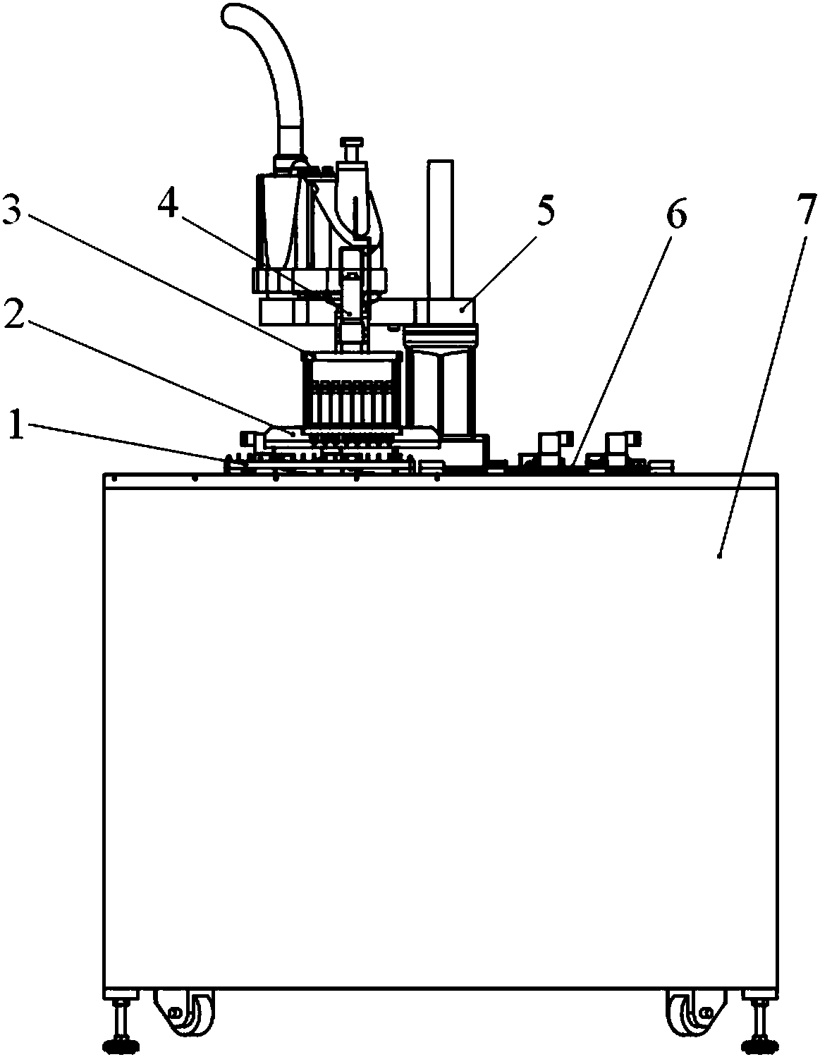
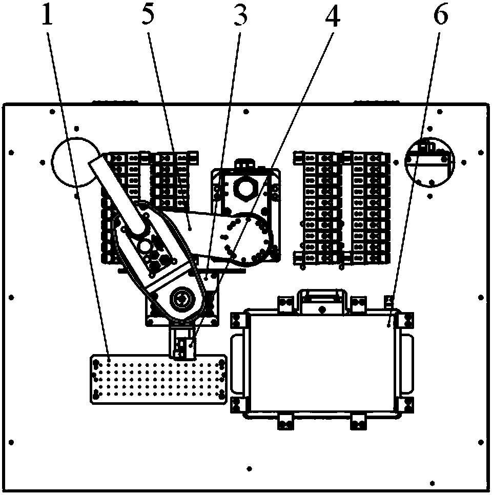
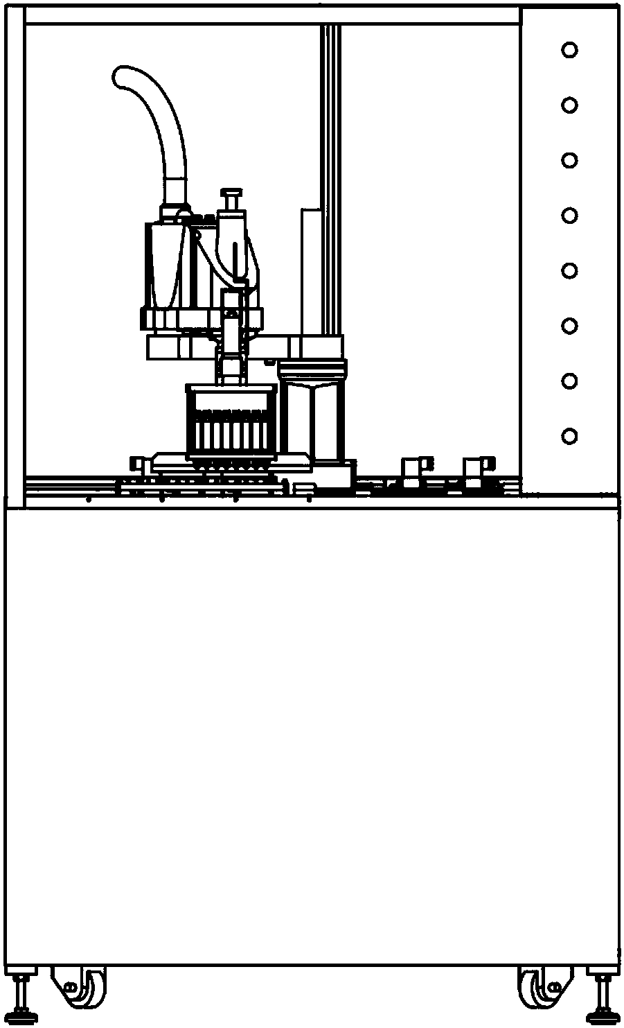
[0032] A ball grid array structure chip blanking equipment, its structure is as follows Figure 1-2 As shown, the equipment consists of a chip tray placement platform 1, an array mechanism 2, a vacuum pick-and-place mechanism 3, a CCD detection mechanism 4, a robot arm 5, and a reflow soldering iron plate conveying mechanism 6, which are erected on the bottom platform and the control system 7. Can also be provided with top safety cover on the bottom platform and control system 7, as image 3 As shown, the chip tray placement platform 1, the array mechanism 2, the vacuum pick-and-place mechanism 3, the CCD detection mechanism 4, the robot arm 5, and the reflow iron plate conveying mechanism 6 are all set in the safety cover.

[0033] The local structure of vacuum pick-and-place mechanism, array mechanism, and CCD detection mechanism is as follows: Figure 4-5 As shown, wherein, the array mechanism 2 is composed of an array plate 21, a pillar 22, a connecting plate 23 and a fix...


PUM


Abstract

The invention relates to a ball grid array structure chip blanking device, which consists of a chip tray placement platform (1), an array mechanism (2), a vacuum pick-and-place mechanism (3), a CCD set up on a bottom platform and a control system (7). Composed of detection mechanism (4), robot arm (5), and reflow soldering iron plate conveying mechanism (6), chip tray placement platform (1) and reflow soldering iron plate conveying mechanism (6) respectively place trays and iron plates with chips , the array mechanism (2), the vacuum pick-and-place mechanism (3), and the CCD detection mechanism (4) are mounted on the robot arm (5). Compared with the prior art, the invention can automatically complete quality screening, improve production efficiency, and is simple to operate and easy to use.

Description

technical field [0001] The invention relates to a blanking device, in particular to a chip blanking device with a ball grid array structure. Background technique [0002] BGA (Ball Grid Array) packaging technology began in the 1960s. With the successful development of high-end packaging equipment such as ball planting machines, it has now become the mainstream packaging method in the market. In actual production, BGA chips are relatively expensive, and chip damage is often only the damage of solder ball pins, and its internal circuit is intact. Therefore, chip rework becomes very necessary. At present, there are three ways to repair chips: manual repair, simple repair device, and chip repair ball planting machine. Manual rework and simple rework devices can only perform rework on a small number of chips, with low efficiency and low output. Although the chip rework and ball planting machine is relatively expensive, its high productivity has greatly reduced the price of BGA...

Claims


Application Information

Patent Timeline
Patent Type & Authority Patents(China)
IPC IPC(8): B07C5/34B07C5/36
Inventor 张金志钟亮石洋毕秋吉时威
Owner 江苏弘琪工业自动化有限公司
Learn More