
A cement combined grinding system

A combined grinding and cement technology, which is applied in cement production, solid separation, and separation of solids from solids with airflow, can solve the problems of low power consumption, complex system, and low grinding efficiency of cement grinding, and achieve Good material dispersion, improved separation efficiency, and small pressure loss

Active Publication Date: 2018-04-27
SINOMA LIYANG HEAVY MACHINERY
View PDF6 Cites 0 Cited by
  • Summary
  • Abstract
  • Description
  • Claims
  • Application Information

AI Technical Summary

Problems solved by technology

The ball mill system has a high operating rate, excellent cement particle appearance, and good product quality, but has low grinding efficiency, high power consumption, and low output; the final grinding system of the vertical mill has high grinding efficiency and low unit power consumption, but due to its production Cement particle gradation and particle morphology are poor, resulting in large cement water demand, poor early strength, and subsequent concrete operability and durability problems, which are rarely used at this stage; combined grinding of pre-grinding equipment and ball mills The system combines the advantages of the former two grinding systems. Not only the grinding efficiency is high, but also the characteristics of cement particles have been significantly improved. The physical properties of cement are excellent, the power consumption of cement grinding is low, and the output is high. The pre-grinding equipment in the cement industry mainly includes roller presses and vertical mills. Among them, the system equipment using roller presses requires large civil construction investment, complex systems, high failure rates, and difficult maintenance

Method used


Image

  • A cement combined grinding system
  • A cement combined grinding system
  • A cement combined grinding system

Examples


Embodiment Construction

[0018] The technical solution of the present invention will be further described below in conjunction with the accompanying drawings.

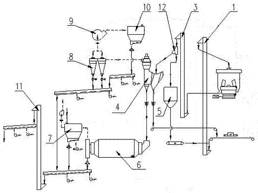
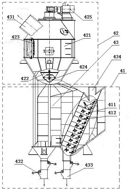
[0019] combine figure 1 , a cement combined grinding system, including a feed hoist 1, a pre-grinding vertical mill, an outer circulation hoist 3, a dynamic and static combination composed of a cage-type dynamic classifier 42 and a V-shaped static classifier 41 connected in series up and down Type three separation powder separator 4, ball mill 6, storage elevator 11, the raw materials enter the pre-grinding vertical mill through the feed elevator 1 and obtain fine powder, medium coarse powder and coarse powder, fine powder, medium coarse powder and coarse powder The powder enters the dynamic and static combined three-separation powder separator 4 from the inlet 434 of the V-type static powder separator 41 through the external circulation elevator 3, and then outputs in three ways: the fine powder enters the cyclone 8 from the fine powder port ...


PUM


Abstract

The invention discloses a cement combined grinding system. Raw materials enter a pre-grinding vertical mil by virtue of a feeding lifter, so that fine powder, medium-coarse powder and coarse powder are obtained; the fine powder, the medium-coarse powder and the coarse powder enter a dynamic and static combined type three-separation powder concentrator from an inlet of a V-shaped powder concentrator for being output in three parts; the fine powder enters a cyclone cluster from a fine powder opening of a cage-shaped dynamic powder concentrator and is warehoused by virtue of a warehousing lifter; the medium-coarse powder enters a ball mill from a medium-coarse powder opening of the V-shaped static powder concentrator, so that fine powder is obtained, and then, the fine powder is warehoused by virtue of the warehousing lifter; and the coarse powder is recycled into the pre-grinding vertical mill from a coarse powder opening of the V-shaped static powder concentrator for being re-grinded. According to the invention, by virtue of the system which consists of the pre-grinding vertical mill, the ball mill and the dynamic and static combined type three-separation powder concentrator, adaption to different materials and different system states is improved by virtue of a series of regulations, so that the optical balance point is found, the graduation efficiency is improved, and the energy consumption is reduced, and therefore, product particle shapes and a product particle formula are improved.

Description

technical field [0001] The invention relates to the technical field of cement production, in particular to a cement grinding system. Background technique [0002] At present, there are mainly three types of cement grinding systems: ball mill system, combined grinding system of pre-grinding equipment and ball mill, and final grinding system of vertical mill. The ball mill system has a high operating rate, excellent cement particle appearance, and good product quality, but has low grinding efficiency, high power consumption, and low output; the final grinding system of the vertical mill has high grinding efficiency and low unit power consumption, but due to its production Cement particle gradation and particle morphology are poor, resulting in large cement water demand, poor early strength, and subsequent concrete operability and durability problems, which are rarely used at this stage; combined grinding of pre-grinding equipment and ball mills The system combines the advanta...

Claims


Application Information

Patent Timeline
Patent Type & Authority Patents(China)
IPC IPC(8): B02C21/00B02C23/14B02C23/20B07B7/08C04B7/52
CPCB02C21/00B02C23/14B02C23/20B07B7/08C04B7/52Y02P40/10
Inventor 吴楠谈志中陈悠封士洋王跃军
Owner SINOMA LIYANG HEAVY MACHINERY
Learn More