
led driver

A LED driving and driving current technology, which is applied in the semiconductor field, can solve the problems of high cost, affecting the service life of LED, and unable to adjust the light, so as to achieve the effect of low cost and improved user experience

Active Publication Date: 2018-09-11
BYD SEMICON CO LTD
View PDF5 Cites 0 Cited by
  • Summary
  • Abstract
  • Description
  • Claims
  • Application Information

AI Technical Summary

Problems solved by technology

[0003] However, related technologies cannot well meet the requirements of users. For example, the disadvantage of linear dimming is that the dimming signal is a DC analog signal, and its stability needs to be considered. If it is unstable, it will cause the LED to appear slightly flickering; or such as PWM Dimming controls the working time of the system by using a PWM signal lower than the normal operating frequency, but if there is a large current ripple on the LED load, it will affect the life of the LED; or for example, Triac dimming through a special dimmer , which will lead to high cost and low conversion efficiency, and because the internal parameters of each dimmer are different, it will cause the problem that the LED driver is not compatible with the dimmer and cannot be dimmed; or for example, the switch segment dimming through the switch Action to adjust the brightness of the LED, but the brightness of the LED in this dimming method is discontinuous, and only a few fixed brightness can be output, which greatly reduces the user experience effect

Method used


Image

  • led driver
  • led driver
  • led driver

Examples


Embodiment Construction

[0016] Embodiments of the present invention are described in detail below, examples of which are shown in the drawings, wherein the same or similar reference numerals designate the same or similar elements or elements having the same or similar functions throughout. The embodiments described below by referring to the figures are exemplary and are intended to explain the present invention and should not be construed as limiting the present invention.

[0017] In addition, the terms "first" and "second" are used for descriptive purposes only, and cannot be interpreted as indicating or implying relative importance or implicitly specifying the quantity of indicated technical features. Thus, a feature defined as "first" and "second" may explicitly or implicitly include one or more of these features. In the description of the present invention, "plurality" means two or more, unless otherwise specifically defined.

[0018] In the present invention, unless otherwise clearly specified...


PUM


Abstract

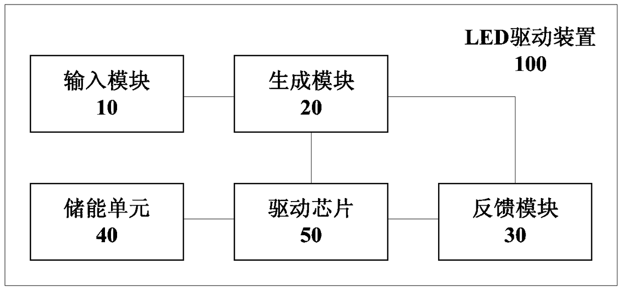
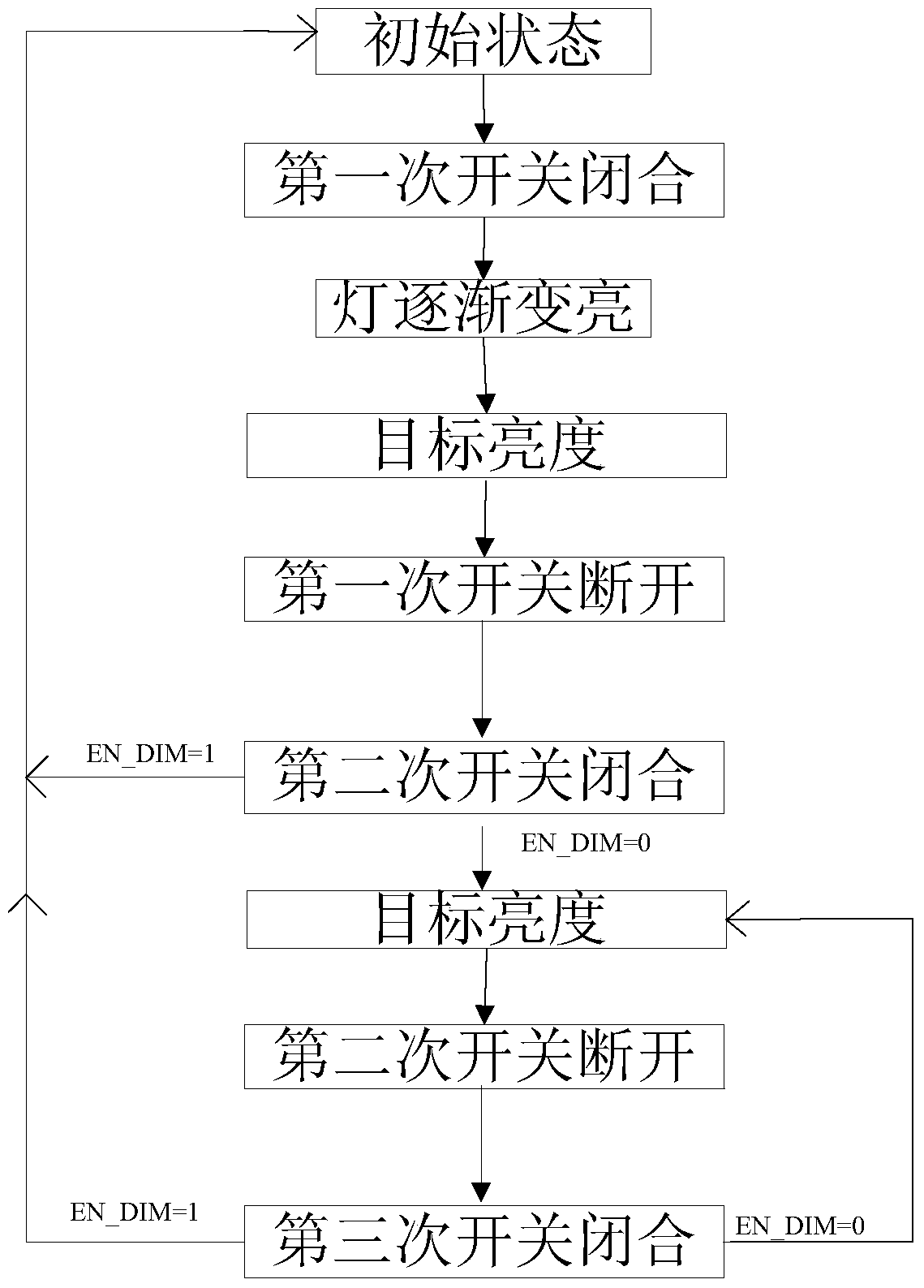
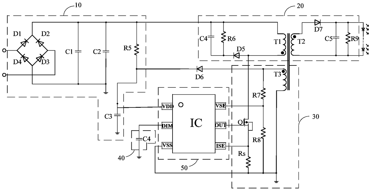
The invention discloses an LED driving device, comprising: an input module; a generation module for generating driving current; a feedback module for collecting the driving current and generating a feedback signal; an energy storage unit; Charge, and control the drive current according to the voltage and feedback signal to adjust the brightness, when the switch is turned off for the first time and then closed for the second time, if the time interval between the first time off and the second time of closure meets the preset If the conditions are set, after the second closing, the brightness of the LED when it is turned off for the first time is used as the driving chip for the working brightness. The device charges the energy storage unit after the switch is closed for the first time, and controls the driving current through voltage and feedback signals to adjust the brightness of the LED. After the switch is closed for the second time, if the time interval meets the preset conditions, The brightness of the LED when it is turned off for the first time is used as the working brightness of the LED to realize stepless dimming.

Description

technical field [0001] The invention relates to the technical field of semiconductors, in particular to an LED driving device. Background technique [0002] In related technologies, LED (Light-Emitting Diode, light-emitting diode) dimming technologies include linear dimming, PWM (Pulse Width Modulation, pulse width modulation) dimming, Triac dimming, and switch segment dimming. Among them, dimming technology generally adds corresponding circuits inside the LED driver chip, and adds devices outside the LED driver chip, and realizes dimming through the mutual cooperation between the circuit and the device. [0003] However, related technologies cannot well meet the requirements of users. For example, the disadvantage of linear dimming is that the dimming signal is a DC analog signal, and its stability needs to be considered. If it is unstable, it will cause the LED to appear slightly flickering; or such as PWM Dimming controls the working time of the system by using a PWM sig...

Claims


Application Information

Patent Timeline
Patent Type & Authority Patents(China)
IPC IPC(8): H05B37/02H02M3/28
CPCH05B45/39Y02B20/30
Inventor 蒋幸福王文情
Owner BYD SEMICON CO LTD
Learn More