Motor iron core molding die

A technology for forming molds and iron cores, which is used in the manufacture of stator/rotor bodies, etc., and can solve the problems of low concentricity of silicon steel sheets, reduced machining accuracy of motor iron cores, and uneven force on the rotor seat.

Inactive Publication Date: 2016-03-23
无锡高晟成型科技有限公司
View PDF15 Cites 4 Cited by
  • Summary
  • Abstract
  • Description
  • Claims
  • Application Information

AI Technical Summary

Problems solved by technology

[0002] The forming process of the motor iron core is to stamp and form the silicon steel sheet, then superimpose stamping and forming on multiple silicon steel sheets, and the stamped silicon steel sheet is superimposed and stamped in the rotor seat. The balance of the silicon steel sheet is eliminated to eliminate the superposition error of the silicon steel sheet. After a stamping is completed, the rotor seat must be rotated to ensure that the different points of the silicon steel sheet are stressed. The rotor seat in the existing superimposed stamping mold drives the rotor seat to rotate through the rotation of the screw. In this way of rotation, the rotor seat can only rotate step by step at a small angle to realize the circular rotation of the rotor seat. The rotor seat rotates step by step through a small angle to prevent the accumulation of silicon steel sheets when the silicon steel sheets of the rotor seat are stacked and stamped. error, resulting in low concentricity of the silicon steel sheet, and the silicon steel sheet is stressed step by step in one direction, which makes the parallelism and perpendicularity of the superimposed silicon steel sheet low, which makes the produced motor noisy, and the force on the rotor seat is not strong. Uniformity, so that the wear of the needle sleeve and the rotor seat is serious, reducing the machining accuracy of the motor core

Method used


Image

  • Motor iron core molding die
  • Motor iron core molding die
  • Motor iron core molding die

Examples


Embodiment Construction

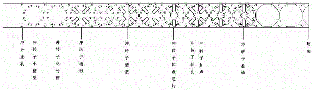
[0010] See figure 1 , figure 2 , a motor core forming die, which includes a stamping forming device 1, a superimposed stamping forming device 2 and a waste cutting device 3, the superimposing stamping forming device 2 includes a punching rotor stacking die head 4 and a rotor seat 5, and a punching rotor stacking die The head 4 is set on the upper mold 6, the rotor base 5 is set on the lower mold 7, the rotor base 5 is set with a needle roller sleeve 8, the rotor base 5 is connected to the servo motor 10 through the belt 9, and the rotation angle of the rotor base is controlled by the servo motor. Make the stacking riveting force evenly act on the iron core and not concentrate on one point, thereby reducing the cumulative error of the stacking of silicon steel sheets, improving the parallelism, verticality and concentricity of the product, and effectively reducing the noise of the motor. The service life of the motor is improved, while the wear of the rotor seat is reduced, a...


PUM


Abstract

The invention provides a motor iron core molding die. The molding die achieves the uniform bearing of a force during the superposed punching molding of silicon steel sheets, reduces the superposed accumulative error of the silicon steel sheets, improves the parallelism degree, verticality and concentricity of products, effectively reduces the noise of a motor, prolongs the service life of the motor, reduces the wear of a rotor seat, and improves the machining precision of a motor iron core. The molding die comprises a punch forming device, a superposed punching molding device, and a waste cutting device. The superposed punching molding device comprises a punching rotor superposed riveting die head and a rotor seat, wherein the punching rotor superposed riveting die head is disposed on an upper die, and the rotor seat is disposed on a lower die. The interior of the rotor seat is provided with a rolling pin sleeve in a sleeving manner. The molding die is characterized in that the rotor seat is connected with a driving device through a belt.

Description

technical field [0001] The invention relates to the technical field of the motor manufacturing field, in particular to a motor iron core forming die. Background technique [0002] The forming process of the motor iron core is to stamp and form the silicon steel sheet, then superimpose stamping and forming on multiple silicon steel sheets, and the stamped silicon steel sheet is superimposed and stamped in the rotor seat. The balance of the silicon steel sheet is eliminated to eliminate the superposition error of the silicon steel sheet. After a stamping is completed, the rotor seat must be rotated to ensure that the different points of the silicon steel sheet are stressed. The rotor seat in the existing superimposed stamping mold drives the rotor seat to rotate through the rotation of the screw. In this way of rotation, the rotor seat can only rotate step by step at a small angle to realize the circular rotation of the rotor seat. The rotor seat rotates step by step through a...

Claims


Application Information

Patent Timeline
Patent Type & Authority Applications(China)
IPC IPC(8): H02K15/02
Inventor 夏小江
Owner 无锡高晟成型科技有限公司
Why Eureka
Try Eureka