Device for measuring expansion rate of oil well cement test block

A technology of oil well cement and measuring device, which is applied in the direction of material thermal expansion coefficient, etc., can solve the problems of unreasonable structural design, high material cost, gas channeling, etc., and achieve the effect of improving measurement accuracy and accuracy and reducing test data error

Active Publication Date: 2016-03-23
JIAHUA SPECIAL CEMENT
View PDF9 Cites 2 Cited by
  • Summary
  • Abstract
  • Description
  • Claims
  • Application Information

AI Technical Summary

Problems solved by technology

[0005] The pavement cement concrete expansion coefficient testing device disclosed in this patent document has an unreasonable structural design. First, it can only detect the expansion rate of cement stone at a curing temperature of 10-50°C, that is, the expansion rate of cement concrete for pavement, and cannot detect more. The expansion rate of cement stone under high ambient temperature; second, the temperature detector needs to be embedded in the cement concrete specimen, which is difficult to recycle and reuse, and the material cost is high; third, the concrete specimen is fixed in the water tank and cannot be moved. During the test age, the displacement sensor cannot be reused
However, the operating environment temperature of oil well cement varies greatly, and the properties of the expansion components of cement vary greatly at different temperatures. Using this device to test the expansion rate of oil well cement, the data obtained has large errors, which cannot be provided for oil well cement on site. Objective data reference makes it easy to form an annular gap between the oil well cement sheath and the formation, resulting in gas channeling, resulting in production safety accidents, and there are also disadvantages in terms of economic performance

Method used


Image

  • Device for measuring expansion rate of oil well cement test block
  • Device for measuring expansion rate of oil well cement test block
  • Device for measuring expansion rate of oil well cement test block

Examples


Embodiment 1

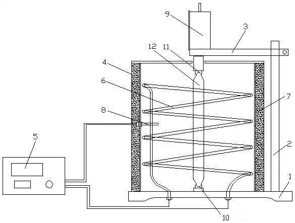
[0041] see figure 1 , a kind of oil well cement test piece expansion ratio measuring device, comprises base 1, column 2 and clamping arm 3, the lower end of column 2 is connected with base 1, the upper end of column 2 is connected with clamping arm 3, also includes thermostatic box 4 and A thermostat 5, the thermostat 4 is fixed on the base 1, the inner wall of the thermostat 4 is connected with a heating pipe 6, the outer wall of the thermostat 4 is connected with an insulation layer 7, and the inner wall of the thermostat 4 is connected with a thermocouple 8. The temperature controller 5 is electrically connected to the thermocouple 8 and the heating tube 6 respectively, the dial indicator 9 is connected to the clamping arm 3, and the lower recess 10 is fixed on the inner bottom wall of the thermostat 4 , the upper recess 11 is fixed on the top wall, the upper recess 11 runs through the top wall of the incubator 4 and is connected with the dial gauge 9, and a standard rod 12...

Embodiment 2

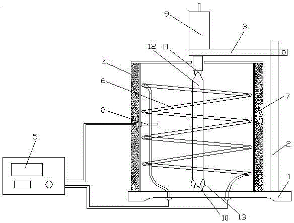
[0044] see figure 2 , a kind of oil well cement test piece expansion ratio measuring device, comprises base 1, column 2 and clamping arm 3, the lower end of column 2 is connected with base 1, the upper end of column 2 is connected with clamping arm 3, also includes thermostatic box 4 and A thermostat 5, the thermostat 4 is fixed on the base 1, the inner wall of the thermostat 4 is connected with a heating pipe 6, the outer wall of the thermostat 4 is connected with an insulation layer 7, and the inner wall of the thermostat 4 is connected with a thermocouple 8. The temperature controller 5 is electrically connected to the thermocouple 8 and the heating tube 6 respectively, the dial indicator 9 is connected to the clamping arm 3, and the lower recess 10 is fixed on the inner bottom wall of the thermostat 4 , the upper recess 11 is fixed on the top wall, the upper recess 11 runs through the top wall of the incubator 4 and is connected with the dial gauge 9, and a standard rod 1...

Embodiment 3

[0048] see figure 2 , a kind of oil well cement test piece expansion ratio measuring device, comprises base 1, column 2 and clamping arm 3, the lower end of column 2 is connected with base 1, the upper end of column 2 is connected with clamping arm 3, also includes thermostatic box 4 and A thermostat 5, the thermostat 4 is fixed on the base 1, the inner wall of the thermostat 4 is connected with a heating pipe 6, the outer wall of the thermostat 4 is connected with an insulation layer 7, and the inner wall of the thermostat 4 is connected with a thermocouple 8. The temperature controller 5 is electrically connected to the thermocouple 8 and the heating tube 6 respectively, the dial indicator 9 is connected to the clamping arm 3, and the lower recess 10 is fixed on the inner bottom wall of the thermostat 4 , the upper recess 11 is fixed on the top wall, the upper recess 11 runs through the top wall of the incubator 4 and is connected with the dial gauge 9, and a standard rod 1...


PUM


Abstract

The invention discloses a device for measuring the expansion rate of an oil well cement test block and belongs to the technical field of cement preparation. The device comprises a base, stand columns and a clamping arm, the lower ends of the stand columns are connected with the base, and the upper ends of the stand columns are connected with the clamping arm; the device is characterized by further comprising a thermotank and a temperature controller, the thermotank is fixed to the base, the inner wall of the thermotank is connected with a heating tube, the outer wall of the thermotank is connected with an insulating layer, the inner wall of the thermotank is connected with a thermocouple, the temperature controller is electrically connected with the thermocouple and the heating tube, the clamping arm is connected with a dial gauge, a downward-recessed seat is fixed to the bottom wall of the interior of the thermotank, an upward-recessed seat is fixed to the top wall, the upward-recessed seat penetrates through the top wall of the thermotank and is connected with the dial gauge, and a standard bar is inlaid between the downward-recessed seat and the upward-recessed seat. By means of the device, the expansion rate of the oil well cement test block can be measured under different environment temperatures, objective data reference is provided for oil well cement under site construction, and the device has the advantages of being high in measurement precision and accuracy.

Description

technical field [0001] The invention relates to the technical field of cement preparation, in particular to a device for measuring the expansion rate of an oil well cement test block. Background technique [0002] In the cementing process of oil and gas wells, gas channeling is a frequently encountered technical problem. Current research shows that there are several factors that lead to gas channeling. During the solidification process of cement slurry, due to the drop of liquid column pressure, shrinkage of cement stone, water loss of cement slurry, etc., an annular gap is formed between the cement sheath and the formation. Under formation pressure, oil and gas move upward along the cracks to other formations or wellheads. Especially in high-pressure wells and natural gas wells, the problem of gas channeling is more prominent, which not only seriously affects the production of oil and gas resources, pollutes other formations, and may even cause serious production safety ac...

Claims


Application Information

Patent Timeline
Patent Type & Authority Applications(China)
IPC IPC(8): G01N25/16
CPCG01N25/16
Inventor 张凌志阳运霞古安林曾雪玲
Owner JIAHUA SPECIAL CEMENT
Why Eureka
Try Eureka