
Telecentric bright field and annular dark field seamlessly fused illumination

A seamless, dark-field technology, used in measurement devices, material analysis by optical means, instruments, etc., can solve the problems of complex systems, failure to seamlessly combine bright-field illumination and dark-field illumination, and expensive

Active Publication Date: 2016-03-23
ORBOTECH LTD
View PDF8 Cites 9 Cited by
  • Summary
  • Abstract
  • Description
  • Claims
  • Application Information

AI Technical Summary

Problems solved by technology

This creates two major problems: stray light from the illumination can easily reach the imaging path; and to combine the illumination and imaging paths, the lower imaging module must be very large, making the system complex and expensive
However, this system also fails to seamlessly combine brightfield and darkfield illumination

Method used


Image

  • Telecentric bright field and annular dark field seamlessly fused illumination
  • Telecentric bright field and annular dark field seamlessly fused illumination
  • Telecentric bright field and annular dark field seamlessly fused illumination

Examples


Embodiment Construction

[0167] In the following detailed description, reference will be made to one or more drawings in which like functional elements are designated by like numerals. The foregoing drawings show, by way of illustration and not by way of limitation, specific embodiments and implementations consistent with the principles of the invention. These embodiments are described in sufficient detail to enable those skilled in the art to practice the invention, and it is to be understood that other embodiments may be utilized and that various elements may be configured without departing from the scope and spirit of the invention. changes and / or substitutions,. Accordingly, the following detailed description should not be construed in a limiting sense.

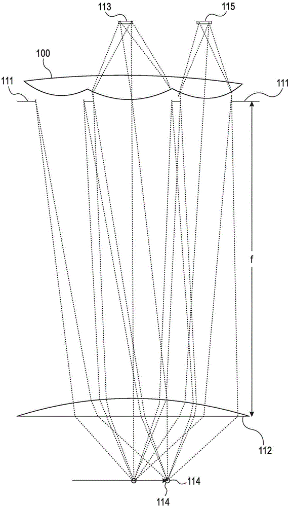
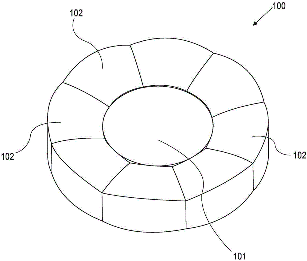
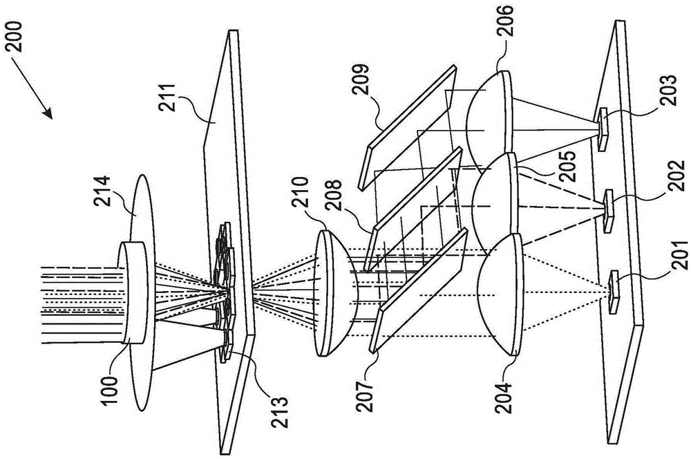
[0168] According to an aspect of the embodiments described herein, there is provided an illumination system for an area inspection apparatus. The illumination provides telecentric brightfield and annular darkfield light that blend seamlessly to...


PUM


Abstract

Described is an illumination system for an area inspection apparatus. The described illumination provides telecentric bright field and annular dark field light that are seamlessly fused together. In one or more embodiments, the illumination system incorporates a unified optical lens assembly that combines different lenses that image illuminations positioned at different planes to a single plane in a seamless way. In one or more embodiments, the different parts of the illumination system have common aperture stop, therefore no vignetting is present in the optical path resulting in high quality of the optical images acquired by the inspection system.

Description

technical field [0001] The present invention relates generally to systems and methods for optical inspection of electronic devices such as LCD and OLED panels, and more particularly to providing seamless telecentric bright field and annular dark field for optical inspection of electronic devices. Fusion irradiation. Background technique [0002] Liquid crystal display (LCD) panels incorporate liquid crystals that exhibit electric field-dependent light modulation properties. The panels are most commonly used to display images and other information in devices ranging from fax machines and laptop computer screens to large screen high-definition TVs. The active matrix LCD panel is a complex layered structure composed of the following functional layers: polarizing film; glass substrate, incorporating thin-film transistors (thin-filmtransistor; TFT), storage capacitors, pixel electrodes, and interconnection wiring; color filter glass substrate, incorporating black matrix, color ...

Claims


Application Information

Patent Timeline
IPC IPC(8): G01N21/01G01N21/88
Inventor T·郝维思E·梅茂
Owner ORBOTECH LTD
Learn More