Small-stroke large-corner dumper lifting machine

A technology of lifting mechanism and large turning angle, which is applied in the direction of loading and unloading vehicles, vehicles used for freight transportation, and vehicles with inclined bearing movement, etc. It can solve the problems of increasing the distance between beams, the length of hydraulic cylinders, and the difficulty of accommodating hydraulic cylinders. To achieve the effect of reasonable structure setting and avoiding excessive load

Inactive Publication Date: 2016-03-23
NINGXIA WANXING FORCE CAR MFG
View PDF6 Cites 3 Cited by
  • Summary
  • Abstract
  • Description
  • Claims
  • Application Information

AI Technical Summary

Problems solved by technology

[0003] There are generally two schemes for the design of the hydraulic lifting mechanism: 1. Install vertically on the end wall of the compartment near the cab; 2. Install on the attached frame under the compartment; the design in scheme 2 currently has the following problems: To ensure the flip angle, the hydraulic cylinder needs to be relatively long, and the relatively long hydraulic cylinder is not easy to be accommodated between the two beams of the attached frame; in this way, either increase the distance between the beams, or the carriage cannot be unloaded. Lays completely flat on attached frame
Either of the above methods will cause the body to be unstable.

Method used


Image

  • Small-stroke large-corner dumper lifting machine
  • Small-stroke large-corner dumper lifting machine
  • Small-stroke large-corner dumper lifting machine

Examples


Embodiment Construction

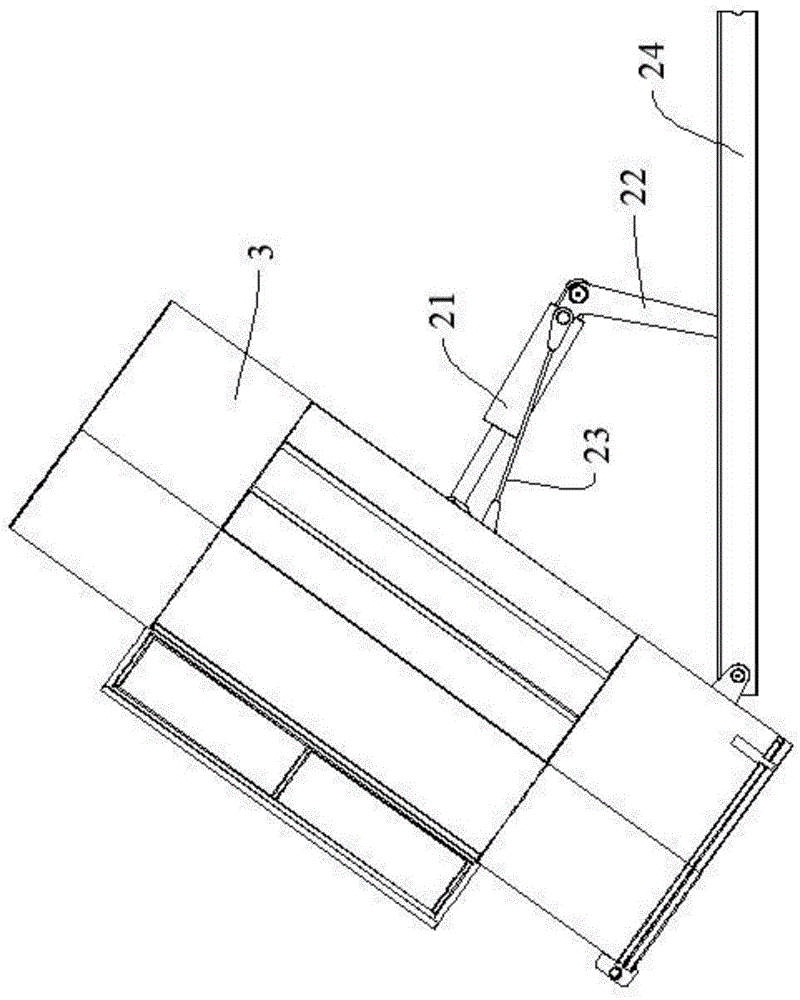
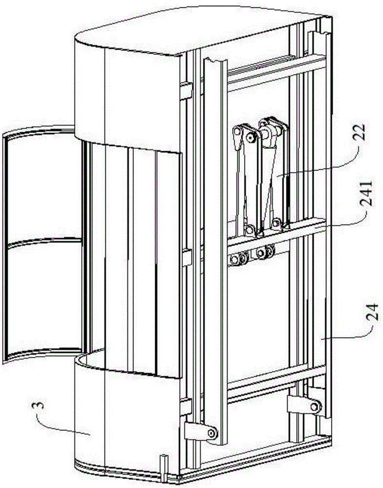
[0018] as attached Figure 1~5 As shown, a dump truck lifting mechanism with a small stroke and a large rotation angle includes: a lifting cylinder 21, a support arm 22, a lifting arm 23, and an attached frame 24; wherein, the fixed end 221 of the support arm is pivotally connected to the attached frame 24 On the side wall of the beam 241 and the side wall is the side close to the driver's cab, the fixed end 221 of the support arm can only rotate around the pivot, but cannot be lifted relative to the attached vehicle frame 24, and the other end of the support arm 22 is the support arm Lifting end 222, the lifting end 222 of the support arm is pivotally connected to one end of the lifting cylinder 21, and the other end of the lifting cylinder 21 is pivotally connected to the bottom of the carriage 3; the "lifting cylinder" involved in the present invention can be a commonly used hydraulic cylinder Cylinder or pneumatic cylinder, etc., as long as the purpose of the present inven...


PUM


Abstract

A small-stroke large-corner dumper lifting machine comprises a lifting cylinder, a supporting arm, a pull-up arm and an attached dumper frame. The fixed end of the supporting arm is pivoted to the side wall of a cross beam of the attached dumper frame, and the lifting end of the supporting arm is pivoted to one end of the lifting cylinder; the other end of the lifting cylinder is pivoted to the bottom of a carriage; the lifting end of the supporting arm is further pivoted to the movable end of the pull-up arm, and the fixed end of the pull-up arm is pivoted to the bottom of the carriage; the distance between two pivot shafts of the lifting cylinder is smaller than the distance between two pivot shafts of the pull-up arm under the non-work state of the lifting cylinder; a supporting arm containing portion is arranged on one side, close to a cab, of the cross beam of the attached dumper frame; and when the lifting cylinder pushes the carriage to rotate, the supporting arm and the pull-up arm drive the lifting cylinder to move in the direction approaching to the carriage, and therefore the lifting cylinder pushes the carriage to finish the large rotation through the short effective stroke; and meanwhile, the lifting machine is reasonable in structural arrangement, the problem that during initial work, loads of the lifting cylinder are too large is solved.

Description

Technical field: [0001] The invention relates to the technical field of special transportation vehicles, in particular to a lifting mechanism for a dump truck with a small stroke and a large turning angle. Background technique: [0002] A dump truck is a type of vehicle that is equipped with a hydraulic system that can tilt the compartment to a certain angle and can unload goods by itself by gravity. It is used for mineral transportation, environmental sanitation and greening or garbage transportation, such as: agricultural dump truck, mine dump truck, garbage dump truck, coal transportation dump truck, etc. Dump trucks include general truck engines, chassis and cabs, as well as hydraulic lifting mechanisms, tiltable compartments and power take-off devices. [0003] There are generally two schemes for the design of the hydraulic lifting mechanism: 1. Install vertically on the end wall of the compartment near the cab; 2. Install on the attached frame under the compartment; t...

Claims


Application Information

Patent Timeline
IPC IPC(8): B60P1/16
CPCB60P1/162
Inventor 金昌林程登雄左都龙
Owner NINGXIA WANXING FORCE CAR MFG
Why Eureka
Try Eureka