


Quick Research
Generate reliable direction feasibility study reports for your R&D in just a few steps.

Technical Q&A
Discover and master advanced knowledge NOW. Basics, ideas, possibilities, all at once.

Find Solutions
As an expert in R&D theories, this can generate solutions to your technical problems instantly.

Evaluate Feasibility
Analyze your overall solution with one click, know your potential R&D risks in advance.

Monitor Landscape
Get weekly tech updates, stay abreast of the latest tech innovations and key insights.
Self-expanding type automobile sunshade
A sunshade, self-expanding technology, applied to vehicle parts, movable outer sheath, transportation and packaging, etc., can solve the problems of high overall height of the sunshade, easy to shake, poor structural stability, etc., and achieve the overall center of gravity Low, easy air flow, good stability
- Summary
- Abstract
- Description
- Claims
- Application Information
AI Technical Summary
Problems solved by technology
Method used
Image

Examples
Embodiment 1
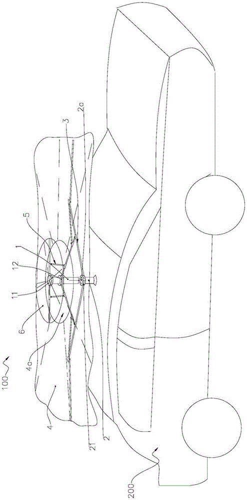
[0051] Such as Figure 1 to Figure 5 As shown, the self-expanding car sun umbrella 100 proposed in this embodiment mainly includes an upper pole body 1, a lower pole body 2, a first umbrella frame 3, and a first umbrella surface 4 laid on the first umbrella frame 3.
[0052] The upper rod body 1 is roughly cylindrical and is made of metal material (of course, plastic, wood or other materials can also be used). The upper rod body 1 is a solid structure (of course, it can also be a hollow structure). In this embodiment, the upper The rod body 1 is equipped with two hinged seats, a first hinged seat 11 and a second hinged seat 12 sleeved on the outer circumference of the upper rod body 1 from top to bottom, wherein the second hinged seat 12 is approximately located at the height of the upper rod body 1. At two thirds, the first hinge base 11 and the second hinge base 12 are made of plastic, and are installed on the upper pole 1 by tight fitting, screws and other existing fixing metho...
Embodiment 2
[0062] Attached below Figure 6 to Figure 9 Only the differences from the first embodiment will be described in detail.
[0063] Image 6 with Figure 7 The self-expanding car sunshade 100 is shown in the folded state, and the distance between the upper pole body 1 and the lower pole body 2 is the farthest. Picture 8 with Picture 9 As shown, the self-expanding car sunshade 100 is in a stretched state, and the bottom of the upper pole body 1 moves into the cavity 2a.
[0064] In this embodiment, a fourth hinge seat 13 is also installed on the upper rod body 1. The fourth hinge seat 13 is arranged at intervals below the second hinge seat 12, and the outer periphery of the fourth hinge seat 13 is provided with a plurality of hinges that open downwards. A plurality of hinge grooves are arranged at intervals along the circumference of the fourth hinge seat 13. A fifth hinge base 22 is also installed on the lower rod body 2. The fifth hinge base 22 is arranged below the third hinge ba...
Embodiment 3
[0066] Attached below Picture 10 Only the differences from the foregoing embodiment will be described in detail.
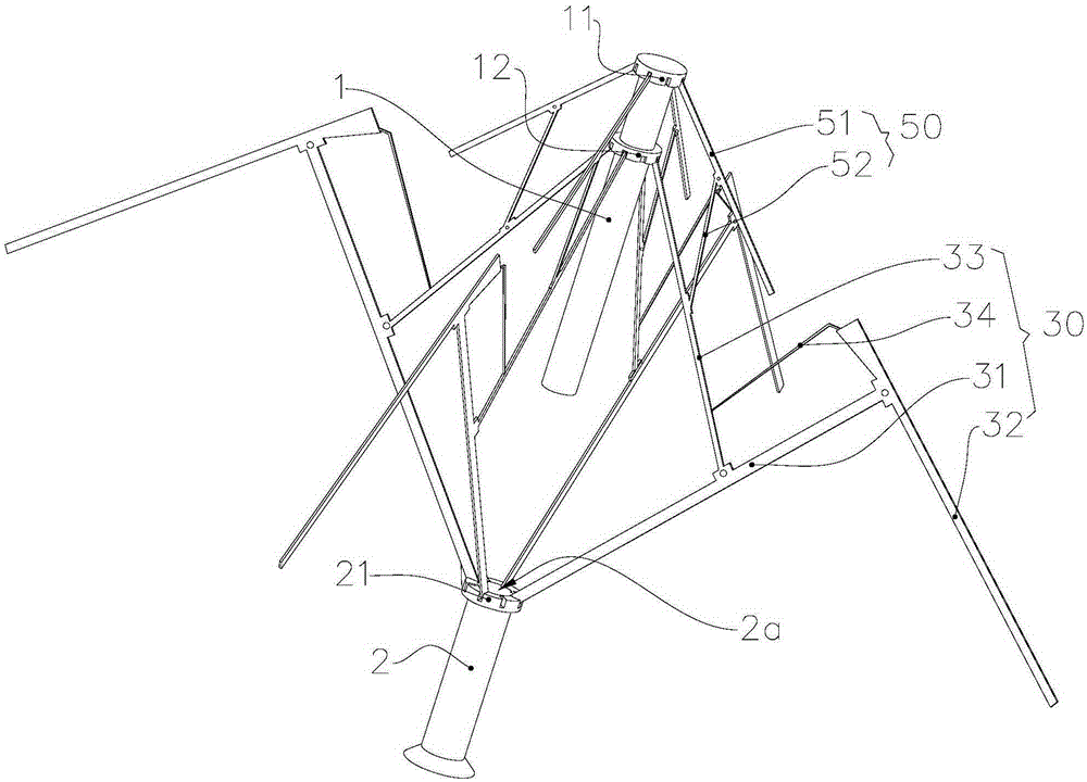
[0067] In this embodiment, the parts that are the same as or corresponding to the second embodiment use the reference numerals corresponding to the second embodiment. In this embodiment, two hinged seats are installed on the upper rod body 1, which are respectively a first hinged seat 11 and a second hinged seat 12 sleeved on the outer circumference of the upper rod body 1 from top to bottom. Two hinge seats are also installed on the lower rod body 2, which are respectively a third hinge seat 21 and a fifth hinge seat 22 sleeved on the outer circumference of the lower rod body 2 from top to bottom.
[0068] The inner ends of the auxiliary ribs 33 in the first rib assemblies 30 of each group are hinged in the hinge groove of the first hinge seat 11, and the outer ends of the auxiliary ribs 33 are hinged to the middle of the inner rib 31. The inner end of the inner rib...
PUM
 Abstract
Description
Claims
Application Information
 - R&D Engineer
- R&D Manager
- IP Professional
- Industry Leading Data Capabilities
- Powerful AI technology
- Patent DNA Extraction
Browse by: Latest US Patents, China's latest patents, Technical Efficacy Thesaurus, Application Domain, Technology Topic, Popular Technical Reports.
© 2024 PatSnap. All rights reserved.Legal|Privacy policy|Modern Slavery Act Transparency Statement|Sitemap|About US| Contact US: help@patsnap.com