
Transformer substation inspection robot system for detecting equipment in box and method thereof

An inspection robot and equipment detection technology, applied in the direction of instruments, manipulators, electrical components, etc., can solve the problems of inability to open the box, reduce the practicality of the substation inspection robot, and cannot realize the detection and operation of equipment in the box, etc., to achieve expansion Device-wide effects

Active Publication Date: 2016-03-23
STATE GRID INTELLIGENCE TECH CO LTD
View PDF5 Cites 50 Cited by
  • Summary
  • Abstract
  • Description
  • Claims
  • Application Information

AI Technical Summary

Problems solved by technology

Existing inspection robots for substations mainly run autonomously along a set fixed route to detect the visible equipment in the substation, but for the electrical equipment inside the box, existing inspection robots for substations cannot to test
And if it is necessary to operate the equipment in the box, the existing robot cannot realize it, thus greatly reducing the practicability of the inspection robot in the substation, making it difficult to realize the real unattended operation of the substation
[0003] At the same time, since the cabinets in substations are usually equipped with locks, which need to be opened manually with a key, the cabinets cannot be opened simply by simply installing the robotic arm of the inspection robot.
For example, the substation intelligent inspection robot involved in the patent No. ZL200910016781.2, although equipped with a mechanical arm, cannot detect and operate the equipment in the box

Method used


Image

  • Transformer substation inspection robot system for detecting equipment in box and method thereof
  • Transformer substation inspection robot system for detecting equipment in box and method thereof
  • Transformer substation inspection robot system for detecting equipment in box and method thereof

Examples


Embodiment Construction

[0038] The present invention will be further described below in conjunction with the accompanying drawings and embodiments.

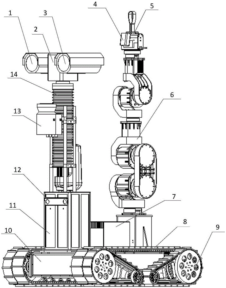
[0039] Such as figure 1 As shown, a substation inspection robot with a mechanical arm includes an inspection robot body and a mechanical arm installed on the body, wherein the robot body includes a wheel-track chassis 10, a cloud platform 2, a platform lifting mechanism 14, a visible light Camera 1, thermal imaging camera 3, laser sensor 13, binocular vision sensor 12 and industrial computer 7. Wherein, the walking mechanism carries the robot body to walk, the mechanical arm is arranged on the walking mechanism, and the industrial computer 7 controls the operation of the acquisition device and the walking mechanism;

[0040] The acquisition device includes a camera, an infrared thermal imager 3, a visual sensor 12 and a laser sensor 13, the visible light camera 1 and the infrared thermal imager 3 are arranged on the cloud platform 2, and the cloud plat...


PUM


Abstract

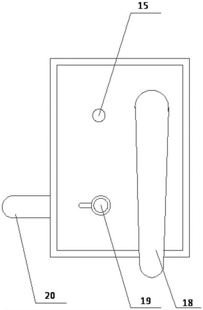
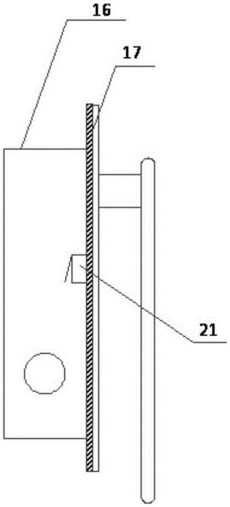
The invention discloses a transformer substation inspection robot system for detecting equipment in a box and a method thereof. The transformer substation inspection robot system comprises a robot and an automatic unlocking system installed outside the box. The automatic unlocking system comprises an electromagnetic lock and a control device. The control device comprises a single-chip microcomputer, a wireless communication module, an electromagnetic relay, a door-closing limiting switch and an alarm module. The automatic unlocking system is installed on a box door. The control device is installed in a lock body. The electromagnetic lock can be remotely controlled to be opened or closed by the robot and can also be manually opened or closed through a key. Through communication with the automatic unlocking system, the box lock can be automatically opened, and therefore detection and operation of the equipment in the box can be realized; the automatic unlocking system is compatible with a common key unlocking mode, and therefore an automatic robot inspection mode and a traditional manual inspection mode can coexist; a robot pan-tilt is provided with a lifting mechanism, and therefore the range of the equipment capable of being detected by the robot is greatly expanded.

Description

technical field [0001] The invention relates to a substation inspection robot system and a method thereof for detecting equipment in a cabinet. Background technique [0002] In recent years, with the development of science and technology, the use of substation inspection robots to automatically complete substation daily equipment inspections, infrared temperature measurement, and equipment status inspections has become an important auxiliary means for substation equipment inspections. Large-scale promotion, unattended substations are becoming more and more common. Existing inspection robots for substations mainly run autonomously along a set fixed route to detect the visible equipment in the substation, but for the electrical equipment inside the box, existing inspection robots for substations cannot to test. And if it is necessary to operate the equipment in the box, the existing robot cannot realize it, thus greatly reducing the practicability of the substation inspectio...

Claims


Application Information

Patent Timeline
IPC IPC(8): B25J11/00B25J5/00G07C9/00H02B3/00
CPCB25J11/00B25J5/005G07C9/0073G07C2009/00865H02B3/00
Inventor 栾怡青王海鹏慕世友郝永鑫娄殿强李建祥赵金龙李丽徐海军肖鹏余振球杨尚伟李希智
Owner STATE GRID INTELLIGENCE TECH CO LTD
Learn More