Eureka AIR delivers breakthrough ideas for toughest innovation challenges, trusted by R&D personnel around the world.

An internal riveting die for hydraulic clutch bearing gland

A clutch bearing and riveting technology, which is applied in the direction of forming tools, manufacturing tools, metal processing equipment, etc., can solve the problems of waste of materials, long time consumption of molds, unfavorable mold management, etc.

Active Publication Date: 2017-11-24
NINGBO HONGXIE CLUTCH
View PDF8 Cites 0 Cited by
  • Summary
  • Abstract
  • Description
  • Claims
  • Application Information

AI Technical Summary

Problems solved by technology

[0002] With the rapid development of the automobile industry, the mechanical release bearing in the automobile separation system is gradually replaced by the hydraulic release bearing. The riveting of the gland in the assembly process of the hydraulic release bearing is often very important. In the past assembly, the riveting The process adopts the riveting of the formal mold, and each model needs to open a different mold. This method has the disadvantages of wasting materials, taking a long time to replace the mold, and not conducive to the management of the mold.

Method used


Image

  • An internal riveting die for hydraulic clutch bearing gland
  • An internal riveting die for hydraulic clutch bearing gland
  • An internal riveting die for hydraulic clutch bearing gland

Examples


Embodiment

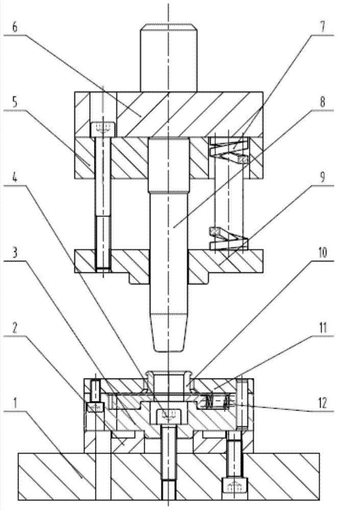
[0028] When it is necessary to rivet the inner hydraulic cover of the hydraulic bearing, first install the mold on the press, install the bottom plate 1 on the press table, and install the lower fixing plate 2 and the lower mold fixing plate 3 through the fixing screws 4 On the bottom plate, select an appropriate split-type lower die insert 10 according to the model of the hydraulic bearing, and install the split-type lower die insert 10 in the lower die fixing plate 3. At the same time, in order to ensure that the split-type lower die insert 10 works More stable, the lower mold cover plate 11 covering the split type lower mold insert 10 is installed on the upper end of the split type lower mold insert 10, and then the lower fixing plate 5 equipped with the connecting plate 6 is passed through the mold handle on the connecting plate 6 The protrusion is connected with the pressure head of the press, and the mandrel 8 is installed in the middle of the lower end face of the lower ...


PUM


Abstract

The invention relates to an inside riveting die of a hydraulic clutch bearing gland. A lower fixing plate is arranged on the upper end face of a bottom plate. A lower die fixing plate is arranged on the upper end face of the lower fixing plate. A split lower die insert is embedded in the middle of the upper end face of the lower die fixing plate. A cylindrical protrusion is arranged in the middle of the upper end face of the split lower die insert. The outer ring of the upper end of the cylindrical protrusion is bent outwards. A locating through hole is formed in the cylindrical protrusion of the split lower die insert. The split lower die insert is evenly divided into multiple fan-shaped columns. The lower portion of each column is transversely provided with a reset spring. A core rod moving up and down is arranged above the locating through hole in the split lower die insert. The lower end of the core rod is of a circular truncated cone columnar structure matched with the locating through hole, wherein the diameter of the lower end of the structure is smaller than that of the upper end of the structure. The inside riveting die of the hydraulic clutch bearing gland has the beneficial effects of being simple in structure, convenient to use, capable of being suitable for hydraulic release bearings of different models, increasing the riveting speed of the bearing glands greatly and meanwhile, improving the riveting strength of the glands and the like.

Description

technical field [0001] The invention relates to the technical field of assembly molds for hydraulic clutch bearings, in particular to an internal riveting mold for hydraulic clutch bearing glands. Background technique [0002] With the rapid development of the automobile industry, the mechanical release bearing in the automobile separation system is gradually replaced by the hydraulic release bearing. The riveting of the gland in the assembly process of the hydraulic release bearing is often very important. In the past assembly, the riveting The process adopts the riveting of the formal mold, and each model needs to open a different mold. This method has the disadvantages of wasting materials, taking a long time to replace the mold, and is not conducive to the management of the mold. In order to overcome these shortcomings, it is necessary to design a new riveting die structure. Contents of the invention [0003] The technical problem to be solved by the present invention...

Claims


Application Information

Patent Timeline
Patent Type & Authority Patents(China)
IPC IPC(8): B21D37/10B21D39/00
CPCB21D37/10B21D39/00
Inventor 徐三刚史浩峰
Owner NINGBO HONGXIE CLUTCH
Why Eureka
Eureka Blog
Learn More