
Shock-absorbing unit for cushioned sole

A shock-absorbing, unitary body technology, applied in the direction of shoe soles, footwear, applications, etc., can solve the problems of unsatisfactory shock-absorbing and shock-absorbing effect, complex structure, large sole volume, etc., achieve good shock-absorbing effect, enhance shock-absorbing ability, The effect of protecting the feet

Inactive Publication Date: 2017-09-29
GUIRENNIAO CO LTD
View PDF2 Cites 0 Cited by
  • Summary
  • Abstract
  • Description
  • Claims
  • Application Information

AI Technical Summary

Problems solved by technology

[0005] The invention provides a shock-absorbing unit for shock-absorbing shoe soles to overcome the existing problems of the existing shock-absorbing structures such as complex structure, cumbersome production process, large sole volume, and unsatisfactory shock-absorbing and shock-absorbing effects.

Method used


Image

  • Shock-absorbing unit for cushioned sole
  • Shock-absorbing unit for cushioned sole
  • Shock-absorbing unit for cushioned sole

Examples


Embodiment approach 1

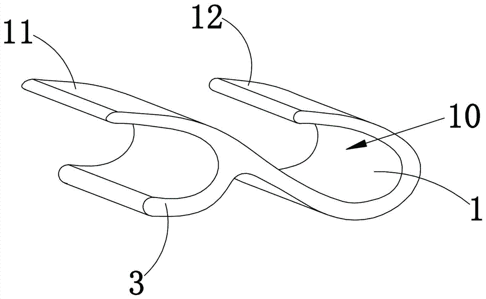
[0020] refer to figure 1 , figure 2 , a shock-absorbing unit for cushioning soles, including a shock-absorbing mechanism A assembled on the sole 2, the shock-absorbing mechanism A is composed of a plurality of unit bodies 1, and the plurality of unit bodies 1 are linear and arranged along the length direction of the sole 2; A slot 10 is formed at the bend of each unit body 1 , and the slot 10 extends along the width direction of the sole 2 . Preferably, the unit body 1 is a TPU unit body 1 , and the sole 2 is an EVA sole 2 . Such as figure 1 , figure 2 , image 3 As shown, the unit body 1 is an elastic member curved in a C shape or oblique U shape, and the opening of the unit body 1 faces obliquely forward, and the two ends of the unit body 1 (front end 11 and rear end 12) The top surfaces are respectively connected with the soles 2 . Such as Figure 1 to Figure 4 As shown in any drawing, the outer wall of the rear end 12 of each unit body 1 is uniformly provided with...

Embodiment approach 2

[0025] The difference between this embodiment and Embodiment 1 is: refer to Figure 5 , in this embodiment

[0026] The adjacent front ends 11 and rear ends 12 of two adjacent unit bodies 1 are integrally connected, the top surfaces of both ends of the unit bodies 1 are respectively connected with the soles 2, and the bottom surfaces of the unit bodies 1 are equipped with anti-slip rubber bottom sheets 4 . The integral connection of two adjacent unit bodies 1 of the shoe sole in this embodiment enables the force between the unit bodies 1 to be transmitted and unloaded, and the impact force on the heel of the shoe sole 2 can be transmitted through this force transmission method. Transfer to the direction of the palm, so that the sole 2 can quickly disperse the impact force received, thereby effectively playing an excellent shock-absorbing function. The sole 2 of this embodiment can basically achieve or even surpass the technical effect that the first embodiment can achieve. . ...


PUM


Abstract

The invention relates to a shock absorption unit for a cushioning sole. The shock absorption unit comprises a shock absorption mechanism assembled on the sole, wherein the shock absorption mechanism comprises at least one unit body; each unit body is a C-shaped elastic piece, the opening of the unit body faces obliquely backwards, top surfaces of two ends of the unit body are connected with the sole respectively, an auxiliary body is arranged on the outer side wall of the back end of the unit body, and the auxiliary body and the back end of the unit body form a C-shaped structure with the backward opening. The unit bodies of the shock absorption unit has good deformation capacity and can decompose and unload treading pressure received by the sole; the auxiliary bodies can provide good support force for the back ends of the unit bodies, the two ends of each unit body and the auxiliary bodies can produce obliquely backward acting force on the sole during treading, impact force between an athlete and the ground is further absorbed effectively, the shock absorption rate of the force is up to 43%-80%, and feet of the athlete can be well protected.

Description

technical field [0001] The invention relates to a component part of a shoe sole, in particular to a shock-absorbing unit for cushioning a shoe sole. Background technique [0002] When exercising, the impact force on the heel of the athlete is three to eight times that of his own body weight. This force will generate shock waves that are more harmful to people, causing damage and pathological changes to tissues such as bones, muscles or joints. For this reason, having the sole of good cushioning function is one of the important ways to solve this problem. The current cushioning soles are mostly made by adding elastic cushioning devices such as air cushions, silicone cushions, and springs, or using materials with large deformations (such as EVA) to make soles, or through cushioning such as honeycomb structures and cushioning protrusions. Structure and other methods to achieve the purpose of cushioning. They either have complex structures, cumbersome production processes, or ...

Claims


Application Information

Patent Timeline
Patent Type & Authority Patents(China)
IPC IPC(8): A43B13/18A43B13/22
CPCA43B13/181A43B13/187A43B13/22
Inventor 林天福陈宗荣
Owner GUIRENNIAO CO LTD
Learn More