
Flat panel dual polarized antenna and composite antenna

A dual-polarized antenna and composite antenna technology, applied in the direction of antenna grounding device, antenna grounding switch structure connection, etc., to increase the beam width and ensure the effect of co-polarization to orthogonal polarization values

Active Publication Date: 2018-03-30
WISTRON NEWEB
View PDF6 Cites 0 Cited by
  • Summary
  • Abstract
  • Description
  • Claims
  • Application Information

AI Technical Summary

Problems solved by technology

[0005] Therefore, the present invention mainly provides a flat dual-polarized antenna to solve the shortcoming of the known antenna beam width (beamwidth, BW) is relatively narrow

Method used


Image

  • Flat panel dual polarized antenna and composite antenna
  • Flat panel dual polarized antenna and composite antenna
  • Flat panel dual polarized antenna and composite antenna

Examples


Embodiment Construction

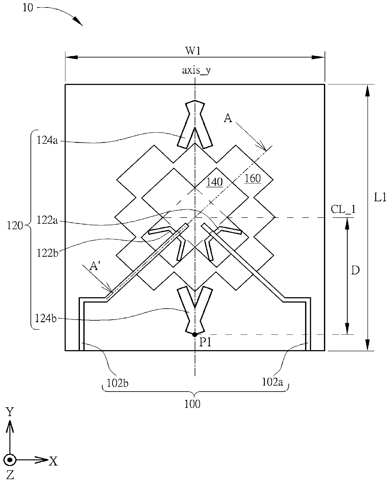
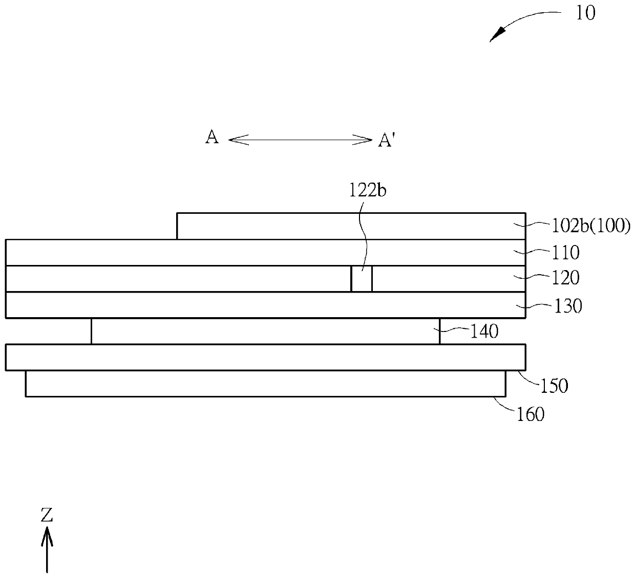
[0054] Please refer to Figure 1A , Figure 1B , Figure 1A Is a schematic top view of a flat dual-polarized antenna 10 according to an embodiment of the present invention, Figure 1B 10 along the flat panel dual-polarized antenna Figure 1A A schematic cross-sectional view of the section line A-A'. The flat panel dual-polarized antenna 10 can be used to transmit and receive radio signals in broadband or multiple frequency bands, such as the signals of Band 40 and 41 in the long-term evolution wireless communication system (the frequency bands are roughly between 2.3GHz~2.4GHz and 2.496GHz~2.690 GHz). Such as Figure 1A , Figure 1B As shown, the planar dual-polarized antenna 10 is roughly a seven-layer structure and has an axisymmetric structure relative to the axis of symmetry axis_y, including a feed-in transmission line layer 100, dielectric layers 110, 130, 150, a grounded metal plate 120, and a microstrip Metal sheets 140,160. The microstrip metal sheet 140 is the main radia...


PUM


Abstract

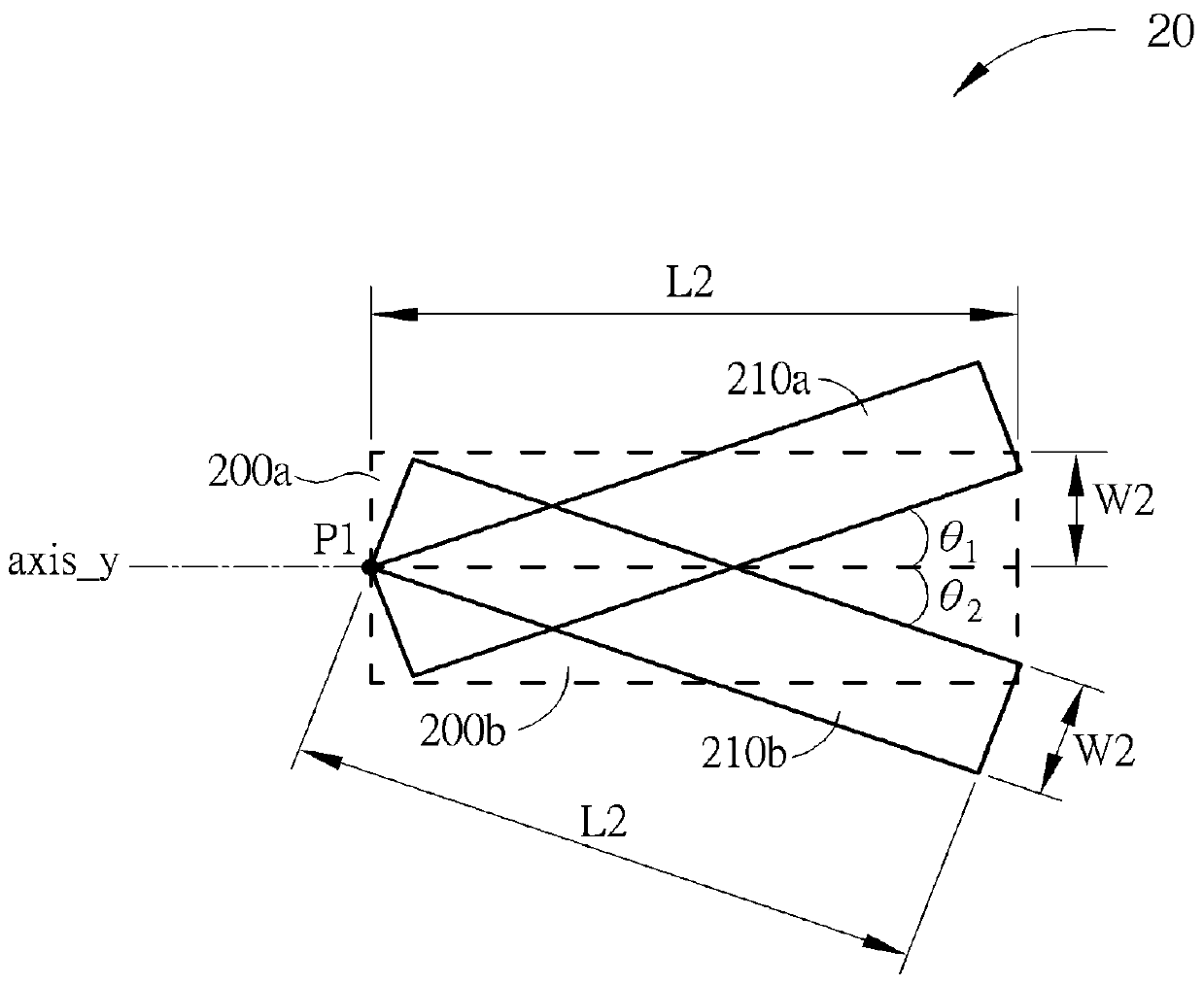
A flat dual-polarized antenna and a compound antenna. The planar dual-polarized antenna is used to send and receive at least one radio signal, and the planar dual-polarized antenna includes: a first microstrip metal sheet; a grounded metal plate, the grounded metal plate includes a first pattern slot and a second A pattern slot, wherein a shape of the first pattern slot consists of a first rectangle and a second rectangle separated by an angle, the first rectangle and the second rectangle coincide at a vertex, and the first pattern The slot hole and the second pattern slot hole are mutually symmetrical to a central axis of the first microstrip metal sheet; and a first dielectric layer formed on the first microstrip metal sheet and the ground metal plate between. The invention can increase the beam width and ensure the orthogonal polarization value of co-polarization pair.

Description

Technical field [0001] The present invention relates to a flat panel dual-polarized antenna and a composite antenna, in particular to a type with broadband, wider beam, high antenna gain, high co-polarization pair orthogonal polarization value (Co / Cx), small antenna size and It can produce flat-panel dual-polarized antennas and composite antennas with an orthogonal dual-polarized antenna field inclined at 45 degrees. Background technique [0002] Electronic products with wireless communication functions, such as notebook computers, personal digital assistants, etc., transmit or receive radio waves through antennas to transmit or exchange radio signals, and then access wireless networks. Therefore, in order to allow users to access the wireless communication network more conveniently, the bandwidth of the ideal antenna should be increased as much as possible within the permitted range, and the size should be reduced as much as possible to cope with the shrinking trend of electroni...

Claims


Application Information

Patent Timeline
Patent Type & Authority Patents(China)
IPC IPC(8): H01Q1/48H01Q1/50
Inventor 徐杰圣詹长庚
Owner WISTRON NEWEB
Learn More