Coupling communication plate based on EtherCAT technology

A technology of communication board and technology, applied in the field of coupling communication board, can solve the problems of low transmission rate and long distance, and achieve the effect of simplified module circuit and simple structure

Inactive Publication Date: 2016-03-16
CHINA ELECTRONICS CORP 6TH RES INST
View PDF6 Cites 11 Cited by
  • Summary
  • Abstract
  • Description
  • Claims
  • Application Information

AI Technical Summary

Problems solved by technology

The two EtherCAT communications have their own advantages and disadvantages. Ethernet 100M transmission requires a physical layer conversion chip, and the distance is long, but the transmission rate is relatively low; while the low-voltage differential signal has a high transmission rate and local high-speed response, but it is only applicable to the PCB of the local module. board level transmission

Method used


Image

  • Coupling communication plate based on EtherCAT technology
  • Coupling communication plate based on EtherCAT technology
  • Coupling communication plate based on EtherCAT technology

Examples


Embodiment 1

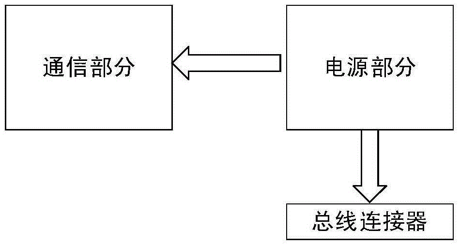
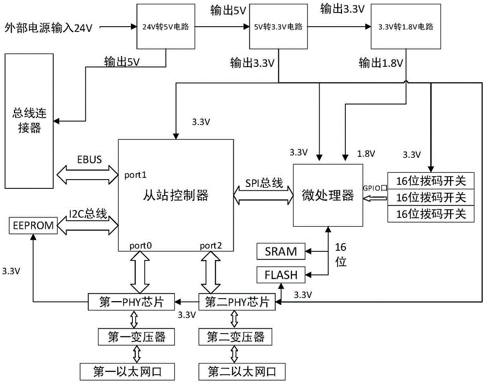
[0035] Such as figure 1 , figure 2 and image 3 As shown, an EtherCAT coupling communication board based on a domestic microprocessor, including a communication part and a power supply part, specifically includes: a microprocessor, a slave station controller, EEPROM, a PHY circuit, a bus connector, 24V to 5V, 5V Convert 3.3V and 3.3V to 1.8V power conversion circuit and Ethernet port.

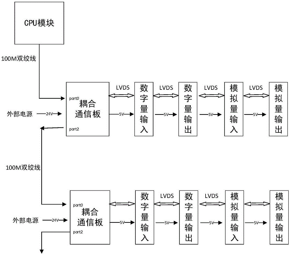
[0036] The communication between the CPU module of the EtherCAT master station and the slave station is through EtherCAT communication, using Ethernet 100M transmission, using 100Base-TX (category five twisted pair) long-distance transmission medium; between each module of the slave station, using EtherCAT bus communication uses EtherCATLVDS signal transmission; the field bus in the design adopts EtherCAT bus, and utilizes its one-net-to-bottom feature.

[0037] In this embodiment, the slave station includes a coupling communication board and a subsequent input and output I / O stack; the sub...


PUM


Abstract

The invention discloses a coupling communication plate based on an EtherCAT technology. The coupling communication plate comprises a controller and a microprocessor connected with the controller through an SPI bus; at least one external communication interface electrically connected with the controller; a bus connector in communication connection with the controller; a power supply conversion chip electrically connected with the bus connector, the controller and the microprocessor; a PHY chip and a transformer which are successively connected between the controller and the external communication interface; and a crystal oscillator for performing time synchronization on the controller and the chip. The coupling communication plate employs a modular physical structure to realize a communication management function between an EtherCAT master station and a slave station and a power supply management function; an input and output module does not have to be directly connected with a master station CPU module, and each module circuit is greatly simplified; and through a power supply conversion circuit, 24V power drawn from an external power source is converted into 5V voltage, the 5V voltage is converted into 3.3V voltage, and the 3.3V voltage is converted into 1.8V voltage.

Description

technical field [0001] The invention relates to the technical field of electrical component design. More specifically, it relates to a coupling communication board based on EtherCAT technology. Background technique [0002] EtherCAT was originally proposed by Beckhoff in Germany based on Ethernet technology. It is a technology with flexible network topology. Its characteristic is that IP / UDP is encapsulated in the protocol, so communication can be realized without IP protocol. EtherCAT technology has the following advantages: fast speed and synchronous transmission; the price of the system is lower than that of the field bus; it can be realized in hardware during real-time communication; it supports multiple topologies; it supports the communication between multiple mechanisms composed of the master station and the slave station ; Standard Ethernet frame; fully open technology; high bandwidth utilization, one network to the end, etc. The EtherCAT system is a master statio...

Claims


Application Information

Patent Timeline
Patent Type & Authority Applications(China)
IPC IPC(8): G05B19/042
CPCG05B19/0421G05B2219/23269
Inventor 武亚鹏王永利于洋马国荣吴金铎
Owner CHINA ELECTRONICS CORP 6TH RES INST
Why Eureka
Try Eureka