
Method for detecting concrete structure crack width by means of fiber sensor

A concrete structure and optical fiber sensor technology, which is applied in the direction of using optical devices, instruments, measuring devices, etc., can solve the problems of inaccurate measurement of crack width, etc., and achieve the effects of reducing labor intensity, improving calculation accuracy, and fast calculation

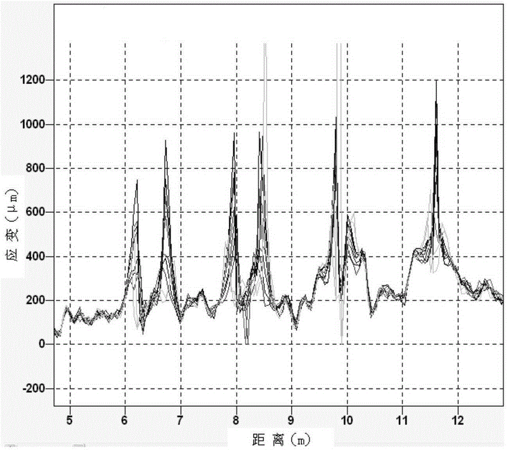
Inactive Publication Date: 2016-03-16
HARBIN INST OF TECH SHENZHEN GRADUATE SCHOOL
View PDF9 Cites 13 Cited by
  • Summary
  • Abstract
  • Description
  • Claims
  • Application Information

AI Technical Summary

Problems solved by technology

[0009] In order to solve the problem that the existing optical fiber sensor cannot accurately measure the width of the crack due to the relative slip between the optical fiber at

Method used


Image

  • Method for detecting concrete structure crack width by means of fiber sensor
  • Method for detecting concrete structure crack width by means of fiber sensor
  • Method for detecting concrete structure crack width by means of fiber sensor

Examples


specific Embodiment approach 1

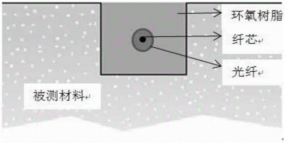
[0054] Specific Embodiments 1. A method for detecting the crack width of a concrete structure using an optical fiber sensor described in this embodiment is carried out in the following steps:

[0055] 1. The formula for calculating the crack width of concrete structures under theoretical conditions:

[0056] Theoretical conditions:

[0057](1) When cracks appear in the concrete structure, the positions on both sides of the crack will be unloaded, and the strain will become smaller;

[0058] (2) Assuming that a crack with a width of w is generated on the surface of the concrete structure, the strain on both sides of the crack is 0, and gradually increases toward the two sides of the crack as the distance from the crack increases. When the tensile strain at a certain point reaches the ultimate tensile strain, Then new cracks will appear at this time;

[0059] (3) The width of the crack in the concrete structure is w, and the length of the optical fiber slip section is L. Assum...


PUM

PropertyMeasurementUnit
Thicknessaaaaaaaaaa

Abstract

The invention provides a method for detecting concrete structure crack width by means of a fiber sensor, relating to a calculating method of concrete structure crack width. The invention aims to solve the problem that a fiber sensor in the prior art cannot accurately measure the crack width because the fiber at the crack and the concrete to be measured generate relative slipping. The method for detecting concrete structure crack width by means of the fiber sensor includes the following steps of concrete crack width calculation formula under the theoretical condition; further simplification of the concrete crack width calculation formula under the theoretical condition; and corrected concrete crack width calculation formula. The method provided improves the calculation accuracy of the concrete crack width and can be applied to the field of building construction.

Description

technical field [0001] The invention relates to a method for detecting the crack width of a concrete structure, in particular to a method for detecting the crack width of a concrete structure by using an optical fiber sensor. Background technique [0002] Optical fiber, also known as optical fiber, is a glass fiber whose main material is silica. When the light wave propagates in the fiber, it is totally reflected at the interface, is confined in the fiber interface and propagates along the axis of the fiber. When the optical fiber is strained, it will affect the propagation of light waves in the optical fiber, and people can obtain the strain information of the optical fiber by detecting the change of optical wave. According to this principle, people invented the fiber optic sensor. [0003] Previously, it was proposed to use the peak value of the optical fiber sensor at the crack to judge the crack width. The optical fiber sensor will have a strain peak at the position w...

Claims


Application Information

Patent Timeline
IPC IPC(8): G01B11/02
CPCG01B11/02
Inventor 段忠东张宝祥
Owner HARBIN INST OF TECH SHENZHEN GRADUATE SCHOOL
Learn More