
tumbler for tea dryer

A technology of tea dryer and tumbler, which is applied in the direction of dryer, tea drying, drying, etc., which can solve problems such as uneven drying of tea, affecting tea quality, and affecting drying efficiency, so as to improve iron removal efficiency , save energy and improve drying efficiency

Active Publication Date: 2017-11-17
HUNAN HAOFENG TEA IND
View PDF6 Cites 0 Cited by
  • Summary
  • Abstract
  • Description
  • Claims
  • Application Information

AI Technical Summary

Problems solved by technology

[0002] In order to facilitate the storage of tea and prolong its shelf life, it is necessary to dry the tea to reduce the moisture content in the tea. The drying efficiency of the existing drying equipment is not high during the drying process. It affects the drying efficiency and reduces the quality of its products. At the same time, there are often some iron impurities in tea processing, which affects the quality of tea.

Method used


Image

  • tumbler for tea dryer

Examples


Embodiment 1

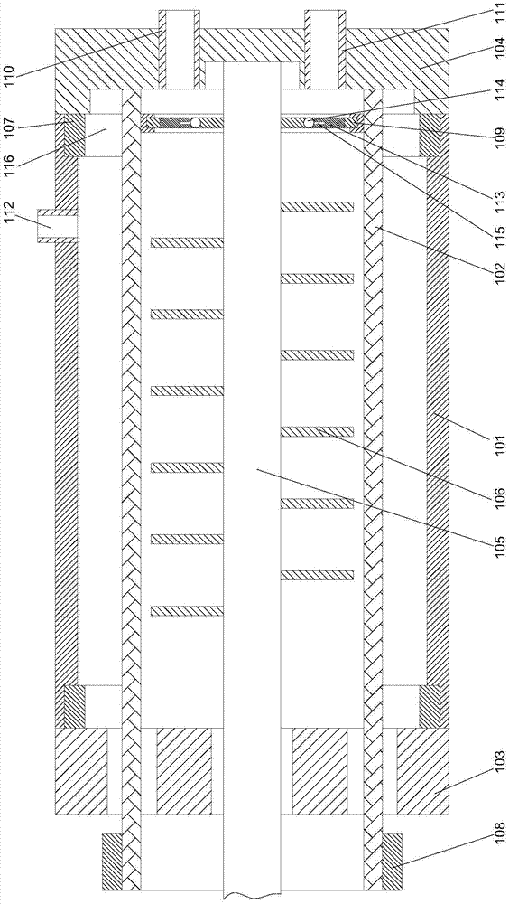
[0020] Such as figure 1 As shown, a tea dryer drum includes a hollow cylindrical housing 101 and a screen 102 arranged inside the housing 101. The screen 102 has a hollow cylindrical structure, and the housing The two ends of the body 101 are respectively provided with a left cover 103 and a right cover 104, and the two ends of the screen 102 are respectively rotatably connected to the left cover 103 and the right cover 104. The middle part is provided with a rotating shaft 105, and blades 106 are arranged on the rotating shaft 105, and the two ends of the rotating shaft 105 are respectively connected to the left cover 103 and the right cover 104 in rotation, and one end of the rotating shaft 105 runs through the The left cover 103, the end of the rotating shaft 105 is located outside the left cover 103, and the inner walls of the housing 101 near the two ends of the left cover 103 and the right cover 104 are respectively provided with The magnet 116 is provided with an input...

Embodiment 2

[0023] In this embodiment, on the basis of Embodiment 1, in order to facilitate the installation of magnets, in this embodiment, preferably, the inner walls of the two ends of the housing 101 close to the left cover 103 and the right cover 104 are respectively provided There is a ring-shaped fixed ring 107 , and a stepped groove is arranged on the inner wall of the fixed ring 107 , and the described magnet 116 is ring-shaped and fixedly connected in the stepped groove on the described fixed ring 107 .

[0024] In order to reduce the powder content in the tea leaves, in this implementation, preferably, one end of the screen 102 is rotatably connected to the right cover 104 through a bearing, and the screen 102 is far away from the right cover 104 One end passes through the left cover 103 , and the outer end surface of the screen 102 away from the right cover 104 is fitted with a ring gear 108 . By setting the ring gear, the ring gear can be driven to rotate by using the driving...


PUM


Abstract

The invention discloses a rotary drum of a tea dryer. The rotary drum comprises a shell in a hollow cylindrical shape and a screen arranged on the inner side of the shell. The screen is of a hollow cylindrical structure. A left sealing cover and a right sealing cover are arranged at the two ends of the shell respectively. The two ends of the screen are rotationally connected to the left sealing cover and the right sealing cover respectively. A rotary shaft is arranged in the middle portion of the shell and provided with blades. The two ends of the rotary shaft are rotationally connected to the left sealing cover and the right sealing cover respectively. One end of the rotary shaft penetrates the left sealing cover. The tail end of the rotary shaft is located on the outer side of the left sealing cover. Magnets are arranged at the positions, close to the inner walls of the two ends of the left sealing cover and the right sealing cover, of the shell respectively. By means of the screen structure, dust in tea is screened; and meanwhile by means of the magnet structure, iron impurities in tea are removed, and the tea quality can be improved.

Description

technical field [0001] The invention relates to a rotating cylinder of a tea dryer. Background technique [0002] In order to facilitate the storage of tea and prolong its shelf life, it is necessary to dry the tea to reduce the moisture content in the tea. The drying efficiency of the existing drying equipment is not high during the drying process. It affects the drying efficiency and reduces the quality of its products. At the same time, there are often some iron impurities in tea processing, which affects the quality of tea. Contents of the invention [0003] The purpose of the present invention is to provide a tea drying machine drum, which can improve the problems existing in the prior art. By adopting a screen structure, the powder in the tea can be sieved, and at the same time, the iron in the tea can be removed by using a magnet structure. impurities, help to improve the quality of tea. [0004] The present invention is realized through the following technical so...

Claims


Application Information

Patent Timeline
Patent Type & Authority Patents(China)
IPC IPC(8): F26B11/14F26B25/04B03C1/30B03C1/02
CPCB03C1/02B03C1/30F26B11/14F26B25/04F26B2200/20
Inventor 银丛格
Owner HUNAN HAOFENG TEA IND
Learn More