Camshaft structure

A camshaft and sprocket technology, which is applied to engine components, machines/engines, mechanical equipment, etc., can solve problems such as inability to adjust, adjustment restrictions, and unfavorable construction, and achieve the effect of simplifying the adjustment process and increasing the adjustment range.

Inactive Publication Date: 2016-03-16
重庆玛斯特机械制造股份有限公司
View PDF0 Cites 0 Cited by
  • Summary
  • Abstract
  • Description
  • Claims
  • Application Information

AI Technical Summary

Problems solved by technology

Usually the sprocket is fixed on the camshaft by screws, so when the user needs to adjust the timing difference between the piston and the valve, the large part of the engine must be disassembled, and then the large part must be reinstalled after adjusting the sprocket angle. The adjustment process is complicated, which is not conducive to construction. At the same time, each adjustment is adjusted in units of pitch, so it cannot be adjusted to a non-integer timing difference such as 0.5 pitch, and the adjustment will be greatly affected. limit

Method used


Image

  • Camshaft structure
  • Camshaft structure

Examples


Embodiment Construction

[0014] Below in conjunction with accompanying drawing and embodiment

[0015] The present invention is described further:

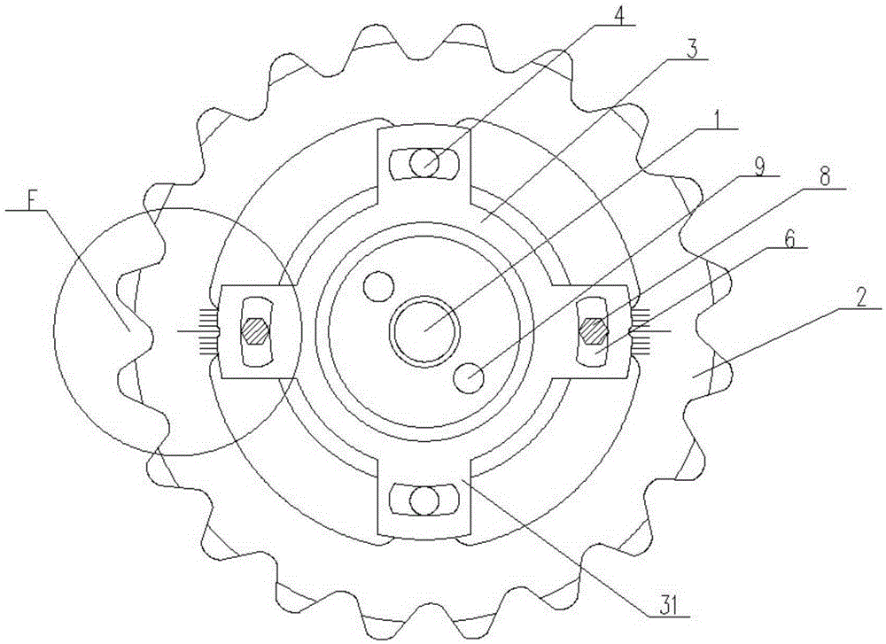
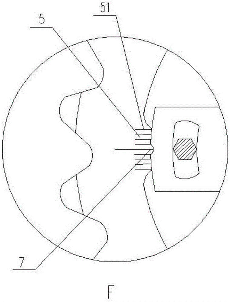
[0016] Such as Figure 1 to Figure 2 As shown, a camshaft structure includes a camshaft 1, a sprocket 2 and a fixed seat 3, the sprocket 2 is fixed to one end of the camshaft 1 through the fixed seat 3, and the sprocket 2 is provided with a first screw hole 4 and a scale 5. The fixed seat 3 is provided with an arc-shaped through hole 6 corresponding to the first screw hole 4, and the fixed seat 3 is provided with an indicator part 7 corresponding to the scale 5. The screw 8 passes through the arc-shaped through hole 6 and is connected with the first screw hole 4.

[0017] The fixed seat 3 is provided with a protruding part 31, and the arc-shaped through hole 6 is arranged on the protruding part 31. The end of the protruding part 31 is provided with an indicating part 7 corresponding to the scale 5, and the number of the protruding parts 31 is 3-6. One, ...


PUM

PropertyMeasurementUnit
Thicknessaaaaaaaaaa

Abstract

The invention discloses a camshaft structure, which comprises a camshaft, a chain wheel and a fixing seat, wherein the chain wheel is fixed to one end of the camshaft through the fixing seat, a first screw hole is formed in the chain wheel and scales are arranged on the chain wheel; an arc-shaped through hole is formed in the part, corresponding to the first screw hole, of the fixing seat, and an indicating part is arranged at the part, corresponding to the scales, of the fixing seat; a screw penetrates through the arc-shaped through hole and is connected with the first screw hole. The scales are added on the camshaft and are matched with the indicating part to adjust the relative positions of the camshaft and the chain wheel, the adjustment range of time sequence errors of a piston and a valve is increased, a fine adjustment effect is achieved, and meanwhile the adjustment process is simplified.

Description

technical field [0001] The invention relates to a camshaft. Background technique [0002] The operation of a general locomotive engine is mainly through the combustion of gasoline in the combustion chamber, thereby driving the piston to reciprocate, and through the rotation of the sprocket to form a linkage with the camshaft, and the rotation of the sprocket will rotate with the crank rotation generated by the reciprocating motion of the piston. The piston and the valve operate synchronously in sequence through the linkage of the cycle, so that the opening and closing of the intake and exhaust valves can cooperate with the piston. Usually the sprocket is fixed on the camshaft by screws, so when the user needs to adjust the timing difference between the piston and the valve, the large part of the engine must be disassembled, and then the large part must be reinstalled after adjusting the sprocket angle. Installing, the adjustment process is complicated, which is not conduciv...

Claims


Application Information

Patent Timeline
IPC IPC(8): F01L1/047F01L1/348
CPCF01L1/047F01L1/348F01L2800/09
Inventor 王彬
Owner 重庆玛斯特机械制造股份有限公司
Why Eureka
Try Eureka