hydraulic percussion drill

A hydraulic percussion and percussion drilling technology, which is applied in the field of hydraulic percussion drilling, can solve the problems of low efficiency, high power consumption and single function, and achieve the effects of convenient use, simple structure and high efficiency

Active Publication Date: 2018-02-09
台州科金中高技术转移有限公司
View PDF10 Cites 0 Cited by
  • Summary
  • Abstract
  • Description
  • Claims
  • Application Information

AI Technical Summary

Problems solved by technology

[0002] Most of the existing medium-sized equipment for drilling holes in stone and concrete are pneumatic and electric; most of the pneumatic drilling rigs are rotary impact type, and the use of pneumatic drilling rigs needs to be equipped with an air compressor, and the air compressor The power of the motor is generally 18.5KW ~ 22KW, and it also needs to be accompanied by a variety of auxiliary equipment; the cost of equipment is high and the power consumption is high
Electric drilling rigs are mostly rotary cutting without impact, and the efficiency is low
For example, when drilling a hole with a diameter of 60mm, it takes more than ten minutes per meter; this results in high cost and low efficiency
Therefore, the impact drilling rigs in the prior art are not only complex in structure and bulky, but also only have rotary impact without cutting function, or only have cutting function without impact function, the function is relatively single, and the scope of application is relatively limited.

Method used


Image

  • hydraulic percussion drill

Examples


Embodiment

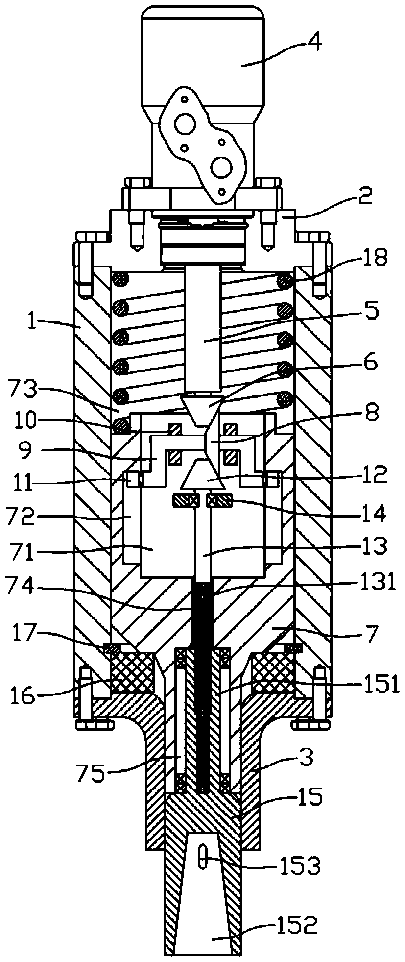
[0014] Example: see figure 1 As shown, a hydraulic impact drill includes a housing 1, the upper and lower ends of the housing 1 are respectively fixedly connected with an upper end cover 2 and a lower end cover 3, and the upper end cover 2 is fixedly connected with a hydraulic motor 4, and the hydraulic motor 4 is connected through a shaft coupling. The device is fixedly connected with a connecting shaft 5, and the lower end of the connecting shaft 5 passes through the upper end cover 2 and is fixedly connected with a vertical driving bevel gear 6, and the driving bevel gear 6 is meshed with a horizontal driven bevel gear 8, and the driven bevel gear 8 is fixed Connected to the middle of the crankshaft 9, the crankshaft 9 is hinged in the housing 1 through the bracket 10; the impact seat 7 is inserted into the housing 1 on the lower side of the crankshaft 9, and a rectangular groove penetrating the upper end surface of the impact seat 7 is formed in the impact seat 7 A hole 71...


PUM


Abstract

The invention discloses a novel hydraulic percussion drill. The upper end and lower end of a housing are respectively fixedly connected with an upper end cover and a lower end cover; the upper end cover is fixedly connected with a hydraulic motor; the hydraulic motor is fixedly connected with a connection shaft via a coupler; the lower end of the connection shaft is fixedly connected with a vertical active bevel gear; the active bevel gear is engaged with a transverse driven bevel gear; the driven bevel gear is fixedly connected to the middle part of a crankshaft; the crankshaft is hinged in the housing via a rack; a percussion seat is inserted into the housing of the lower side of the crankshaft; a rectangular groove hole passing through the upper end surface of the percussion seat is formed in the percussion seat; round recessed platforms are formed on two opposite side walls of the rectangular groove hole; the two ends of the crankshaft are respectively inserted into the recessed platforms on two sides of the rectangular groove hole; an annular groove is formed on the external side of the upper end surface of the percussion seat; a press spring is inserted into the groove; and two ends of the press spring are pressed against the upper end cover and the percussion seat. The hydraulic percussion seat is simply structured, has cutting and impacting functions and has high punching and drilling efficiency.

Description

Technical field: [0001] The invention relates to the technical field of hydraulic tools, and more specifically relates to a hydraulic impact drill. Background technique: [0002] Most of the existing medium-sized equipment for drilling holes in stone and concrete are pneumatic and electric; most of the pneumatic drilling rigs are rotary impact type, and the use of pneumatic drilling rigs needs to be equipped with an air compressor, and the air compressor The power of the motor is generally 18.5KW-22KW, and it also needs to be accompanied by a variety of auxiliary equipment; the cost of the equipment is high and the power consumption is high. Electric drilling rigs are mostly rotary cutting without impact, and the efficiency is low. For example, when drilling a hole with a diameter of 60mm, it takes more than ten minutes per meter; this results in high cost and low efficiency. Therefore, the impact drilling rigs in the prior art are not only complex in structure and bulky, ...

Claims


Application Information

Patent Timeline
Patent Type & Authority Patents(China)
IPC IPC(8): E21B1/14
CPCE21B1/02
Inventor 洪汝频杨爱林
Owner 台州科金中高技术转移有限公司
Why Eureka
Try Eureka