
Head protection device for surgical anesthesia

A protective device and head technology, applied in the field of medical devices, can solve the problems of small breathing space for patients, poor surgical results, and discomfort for patients, and achieve the effects of smooth breathing, simple structure and convenient use.

Inactive Publication Date: 2016-03-16
李海芳
View PDF7 Cites 4 Cited by
  • Summary
  • Abstract
  • Description
  • Claims
  • Application Information

AI Technical Summary

Problems solved by technology

[0002] During the operation, the patient often needs to lie flat on the operating table, and lay a surgical drape on the patient. The surgical drape completely covers the patient, so that the surgical drape is close to the patient's face and the surgical drape is attached to the patient. On the face of the patient, it makes the patient feel uncomfortable, and the space for the patient to breathe is very small, causing the patient to not breathe smoothly, which affects the smooth progress of the operation
At the same time, it is difficult for medical staff to observe the patient's facial expression. It is necessary for the medical staff to lift a corner of the surgical drape with their hands and maintain a certain posture. Unable to observe the patient's facial expression, unable to judge the patient's pain level, etc., unable to increase the dose of anesthetic or take other measures in time, resulting in poor surgical effect and even affecting the smooth progress of the operation

Method used


Image

  • Head protection device for surgical anesthesia
  • Head protection device for surgical anesthesia
  • Head protection device for surgical anesthesia

Examples


Embodiment Construction

[0026] The head protection device for surgical anesthesia of the present invention will be described in detail below with reference to the accompanying drawings.

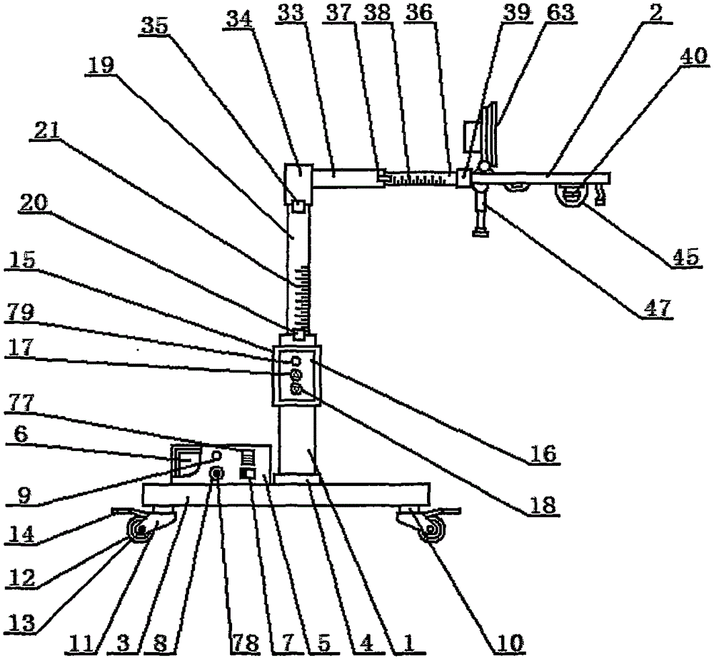
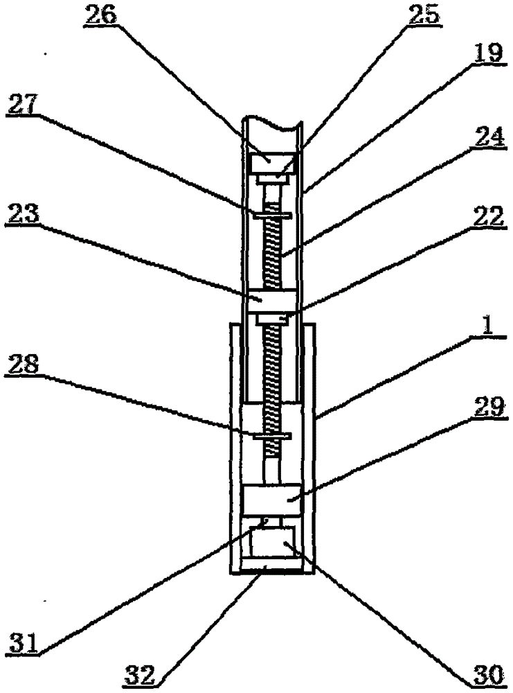
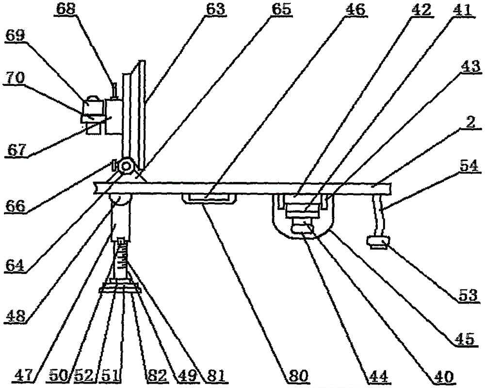
[0027] Such as figure 1 As shown, the surgical anesthesia head protection device of the present invention includes a fixed frame 1 and a head protective frame 2, and a mobile base 3 is provided on the lower side of the fixed frame 1, and the mobile base 3 fixes the connector 4 and the fixed frame 1 through the frame body. Fixed together, the upper side of the mobile base 3 is provided with a mobile power box 5, the mobile power box 5 is provided with a battery pack 6, the front side of the mobile power box 5 is provided with a power control switch 7, and the left side of the power control switch 7 is provided with a charging interface 8. A charging indicator light 9 is provided on the upper side of the charging interface 8, a horizontal rotating shaft 10 is provided on the lower side of the mobile base 3, a moving f...


PUM


Abstract

The invention relates to a head protection device for surgical anesthesia, and belongs to the technical field of a medical apparatus. The head protection device for surgical anesthesia comprises a fixed mount and a head protection rack; an ascending button is arranged on the front side of a lifting control panel; a descending button is arranged on the lower side of the ascending button; a camera is arranged on the lower side of the head protection rack; a camera adjusting holder is arranged on the upper side of the camera; a camera fixing frame is arranged on the upper side of the camera adjusting holder; camera fixing fasteners are arranged on the left side and the right side of the camera fixing frame; a camera adjusting lens is arranged on the lower side of the camera; a liquid crystal display screen is arranged on the left side of the head protection rack; a limiting and connecting rotating shaft is arranged on the lower side of the liquid crystal display screen; and a camera control switch is arranged on the front side of a camera control handle. The head protection device disclosed by the invention is simple in structure and convenient to use; a patient, in an operative process, can breathe more smoothly and doctors can observe facial expression of the patient in real time, so that the dosage of anesthetic is increased or other measures are adopted timely, and the smooth implementation of an operation is guaranteed.

Description

technical field [0001] The invention belongs to the technical field of medical devices, and in particular relates to an operation anesthesia head protection device. Background technique [0002] During the operation, the patient often needs to lie flat on the operating table, and lay a surgical drape on the patient. The surgical drape completely covers the patient, so that the surgical drape is close to the patient's face and the surgical drape is attached to the patient. On the face of the patient, the patient feels uncomfortable, and the space for the patient to breathe is very small, causing the patient to not breathe smoothly, which affects the smooth progress of the operation. At the same time, it is difficult for medical staff to observe the patient's facial expression. It is necessary for the medical staff to lift a corner of the surgical drape with their hands and maintain a certain posture. It is impossible to observe the facial expression of the patient, to judge ...

Claims


Application Information

Patent Timeline
IPC IPC(8): A61B46/20A61B90/00
Inventor 李海芳
Owner 李海芳
Learn More