Flow controlling butterfly valve

A flow control and butterfly valve technology, applied in the field of valve manufacturing, can solve the problems of large valve plate and unfavorable control of pipeline system flow, and achieve the effect of easy rotation, safety of valve and pipeline system, and convenient monitoring

Inactive Publication Date: 2016-03-09
CHENGDU DESHANNENG TECH CO LTD
View PDF7 Cites 4 Cited by
  • Summary
  • Abstract
  • Description
  • Claims
  • Application Information

AI Technical Summary

Problems solved by technology

[0003] When the butterfly valve controls the flow of the valve, because the resistance of the valve plate is very large when the butterfly valve opens part of the valve plate, the impact force of the medium in the valve on the valve plate is also very large, so when the butterfly valve controls the flow in the pipeline , in order to maintain the opening of the valve plate, the force exerted on the valve stem is very large, and it must be maintained continuously, which is not conducive to controlling the flow in the pipeline system

Method used


Image

  • Flow controlling butterfly valve

Examples


Embodiment Construction

[0021] The present invention will be described in detail below in conjunction with the accompanying drawings.

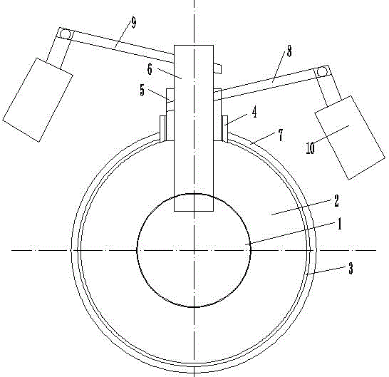
[0022] Such as figure 1 A flow control butterfly valve is shown, which includes an inner valve plate 1, an outer valve plate 2, a valve seat 3, a valve stem frame 4, an inner valve stem 5, an outer valve stem 6, a valve body 7, and a transmission rod Rod 8, b transmission rod 9, electric cylinder 10, the valve body 7 is a cavity structure, the valve seat 3 is installed in the valve body 7, the valve stem frame 4 is installed on the upper part outside the valve body 7, the valve body 7 An inner valve stem 5 and an outer valve stem 6 are installed in the rod frame 4, and a valve plate is installed in the valve body 7, and the valve stem includes an inner valve plate 1 and an outer valve plate 2, and the inner valve plate 1 and the inner valve The valve stem 5 is connected, and the outer valve plate 2 is connected with the outer valve stem 6;

[0023] Among them, the ...


PUM


Abstract

The invention discloses a flow controlling butterfly valve which comprises a valve body, a valve seat and a valve rod rack. The valve body is of a cavity structure. The valve seat is installed in the valve body. The valve rod rack is installed on the upper portion outside the valve body. An inner valve rod and an outer valve rod are installed in the valve rod rack. Valve plates are installed in the valve body and comprise the inner valve plate and the outer valve plate. The inner valve plate is connected with the inner valve rod, and the outer valve plate is connected with the outer valve rod. By means of the butterfly valve, the flow can be adjusted automatically, controlling is convenient, the moment of flow controlling is small, the working condition of the valve can be monitored in real time, and an alarm can be given; automatic control over the valve can be achieved, so that flow controlling of the butterfly valve is more reliable.

Description

technical field [0001] The invention relates to the field of valve manufacturing, in particular to a flow control butterfly valve. Background technique [0002] Butterfly valve Butterfly valve, also called flap valve, is a regulating valve with simple structure, which can be used for switch control of low-pressure pipeline medium. A closed valve. Butterfly valves have become one of the most widely used valves and play a very important role in production. [0003] When the butterfly valve controls the flow of the valve, because the resistance of the valve plate is very large when the butterfly valve opens part of the valve plate, the impact force of the medium in the valve on the valve plate is also very large, so when the butterfly valve controls the flow in the pipeline , in order to maintain the opening of the valve plate, the force exerted on the valve stem is very large, and it must be maintained continuously, which is not conducive to controlling the flow in the pipel...

Claims


Application Information

Patent Timeline
Patent Type & Authority Applications(China)
IPC IPC(8): F16K1/22F16K37/00F16K1/36F16K27/08F16K31/04
CPCF16K1/223F16K27/08F16K31/04F16K37/005
Inventor 李燕
Owner CHENGDU DESHANNENG TECH CO LTD
Why Eureka
Try Eureka