
Full-rigid air spring capable of being locked in any position

An arbitrary position, gas spring technology, applied in the field of gas springs, can solve the problems of difficult to achieve precision, switch activation and rebound force increase, chronic air leakage, etc., to ensure the sealing effect and lifting effect, reduce the processing and assembly time. Difficulty, descent, and ascent values ​​are evenly distributed

Active Publication Date: 2016-03-09
CHANGZHOU LANT GAS SPRING CO LTD
View PDF9 Cites 2 Cited by
  • Summary
  • Abstract
  • Description
  • Claims
  • Application Information

AI Technical Summary

Problems solved by technology

[0002] At present, lockable gas springs are widely used in daily life, especially in office furniture. They are the main components of lifting tables. The tables used in the prior art cannot be rigidly locked, and have elasticity when self-locking. When it is lowered to a low position, the force value is too large, and the operation is very limited
And the adjustment is cumbersome and lacks simplicity
In the prior art, the diameter of the piston valve body and the switch valve needle used in the lockable gas spring is 4MM, and the friction force is relatively large, which causes the start-up and rebound force of the switch to increase, and the assembly and fixing of the piston rod and the piston valve body are relatively In addition, the sealing surface of the inner hole of the sealing end of the piston rod and the piston valve body is difficult to process, it is difficult to achieve the required accuracy, and the processing cost is high, and because of the heat treatment of the surface of the piston rod due to this structural process, the sealing surface of the inner hole cannot be polished. The effect is worse, causing chronic air leakage, oil leakage and other problems

Method used


Image

  • Full-rigid air spring capable of being locked in any position
  • Full-rigid air spring capable of being locked in any position
  • Full-rigid air spring capable of being locked in any position

Examples


Embodiment 1

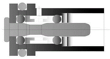
[0023] The air cavity 1 and the oil cavity 2 are separated from the piston 3 and the oil seal 4 by the rear plug 5 located at both ends of the oil pipe. The rear plug 5 is welded to the top of the oil pipe 17 by argon arc welding and sealed. The rear plug 5 is provided with a guide piston 7. Ensure that the oil pipe 17 will not shake from side to side, and the rear end of the oil pipe 17 is reamed so that the piston 3 cannot fall off, and the gas spring can move up and down when it moves up and down. Through the structural design of oil-air separation, the piston rod 6 runs and stretches completely in the oil chamber, so that the locking gas spring can realize full rigid locking at any position and angle, and the floating oil chamber in the air chamber can make the gas spring lift. Press down evenly and easily. One end of the piston rod body 6 is fixedly connected with the piston valve body 8, the center of the piston valve body 8 is provided with a valve needle 13, the contac...

Embodiment 2

[0025] The air cavity 1 and the oil cavity 2 are separated from the piston 3 and the oil seal 4 by the rear plug 5 located at both ends of the oil pipe. The rear plug 5 is welded to the top of the oil pipe 17 by argon arc welding and sealed. The rear plug 5 is provided with a guide piston 7. Ensure that the oil pipe 17 will not shake from side to side, and the rear end of the oil pipe 17 is reamed so that the piston 3 cannot fall off, and the gas spring can move up and down when it moves up and down. Through the structural design of oil-air separation, the piston rod 6 runs and stretches completely in the oil chamber, so that the locking gas spring can realize full rigid locking at any position and angle, and the floating oil chamber in the air chamber can make the gas spring lift. Press down evenly and easily. One end of the piston rod body 6 is fixedly connected with the piston valve body 8, the center of the piston valve body 8 is provided with a valve needle 13, the contac...


PUM


Abstract

The invention relates to the technical field of air springs, in particular to a full-rigid air spring capable of being locked in any position. The full-rigid air spring capable of being locked in any position comprises an outer pipe, an oil pipe, a piston rod body and an ejector rod. The oil pipe is arranged outside the outer pipe. The piston rod body is arranged inside the oil pipe. The ejector rod is arranged inside the piston rod body. A first rear plug is arranged at the top end of the outer pipe. A second rear plug is arranged at the top end of the oil pipe. An air cavity is formed in the outer pipe. An oil cavity is formed in the oil pipe. The air cavity and the oil cavity are separated through an oil seal and pistons. The oil seal is arranged inside the outer pipe and located at the bottom of the oil pipe. The pistons are arranged inside the outer pipe and located on the two sides of the oil pipe. A rear ejecting sleeve is further arranged at the bottom of the outer pipe. According to the full-rigid air spring capable of being locked in any position, by means of the separation mechanism design of the air cavity and the oil cavity, the air spring can be locked in a full-rigid mode in any position and any direction; in addition, the decreasing force value and the increasing force value are uniform, the air spring can be pressed down easily, the limitation of using of the air spring is enlarged, and the user experience effect is improved through the integral structural design.

Description

technical field [0001] The invention relates to a gas spring, in particular to a fully rigid locking gas spring at any position. Background technique [0002] At present, lockable gas springs are widely used in daily life, especially in office furniture. They are the main components of lifting tables. The tables used in the prior art cannot be rigidly locked, and have elasticity when self-locking. When it is lowered to a low position, the force value is too large, and the operation is very limited. And adjustment is loaded down with trivial details, lacks simplicity. In the prior art, the diameter of the piston valve body and the switch valve needle used in the lockable gas spring is 4MM, and the friction force is relatively large, which causes the start-up and rebound force of the switch to increase, and the assembly and fixing of the piston rod and the piston valve body are relatively In addition, the sealing surface of the inner hole of the sealing end of the piston rod...

Claims


Application Information

Patent Timeline
Patent Type & Authority Applications(China)
IPC IPC(8): F16F9/06F16F9/36F16F9/342F16F9/32
CPCF16F9/062F16F9/3214F16F9/342F16F9/368
Inventor 陶声华
Owner CHANGZHOU LANT GAS SPRING CO LTD
Learn More