
Sawing machine

A technology of sawing machine and sliding mechanism, which is applied in the field of sawing machine, can solve the problems of not being able to adapt to the workpiece to be processed, narrow application range, etc., and achieve the effect of low defective rate and less burrs

Active Publication Date: 2016-03-09
江苏铠杰轻合金材料有限公司
View PDF7 Cites 3 Cited by
  • Summary
  • Abstract
  • Description
  • Claims
  • Application Information

AI Technical Summary

Problems solved by technology

With the accumulation of work experience, some operators will place a clamping mechanism on the worktable to clamp the workpiece to be processed, but this type of clamping mechanism cannot adapt to workpieces of different thicknesses, and the scope of application is narrow

Method used


Image

  • Sawing machine

Examples


Embodiment Construction

[0025] Specific embodiments of the present invention will be described in detail below in conjunction with the accompanying drawings. It should be understood that the specific embodiments described here are only used to illustrate and explain the present invention, and are not intended to limit the present invention.

[0026] In the present invention, in the absence of a contrary statement, the orientation words included in the term such as "up, down, left, right, inside, outside" only represent the orientation of the term in the normal use state, or for the purpose of A common term understood by those skilled in the art, and should not be considered as a limitation of the term.

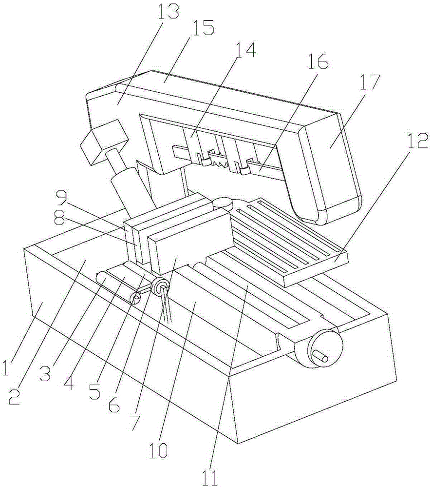
[0027] The invention provides a sawing machine, such as figure 1 As shown, the sawing machine includes an accommodation chamber 2, and the following components arranged inside the accommodation chamber 2: a traction mechanism, a cutting mechanism, a support mechanism and a sliding mechanism; the sup...


PUM


Abstract

The invention discloses a sawing machine which comprises an accommodating chamber, a traction mechanism, a cutting mechanism, a supporting mechanism and a sliding mechanism, wherein the traction mechanism, the cutting mechanism, the supporting mechanism and the sliding mechanism are arranged in the accommodating chamber. The traction mechanism comprises a first traction shaft away from a gap, a second traction shaft close to the gap and a traction table arranged between the first traction shaft and the second traction shaft. The two ends of the second traction shaft are each fixedly sleeved with a flexible rule. The cutting mechanism comprises supporting columns vertically arranged around the supporting mechanism, cutting frames hinged to the supporting columns and cutting pieces arranged on the cutting frames. When moving downwards, the cutting pieces can cut a workpiece to be treated in the gap. A receiving plate is provided with through grooves and arranged under the cutting pieces so as to enable machined finished products to flow into the accommodating chamber from the through grooves. By means of the sawing machine, the defective rate of the finished products after cutting can be lowered, and the application range is wide.

Description

technical field [0001] The present invention relates to cutting equipment, in particular to a sawing machine. Background technique [0002] At present, when cutting the parts to be processed, the parts to be processed are generally placed on the work surface and cut directly, so that the cutting edge of the finished product after cutting is not smooth and has burrs, so the defective rate is high; in addition, the work surface will be damaged . With the accumulation of work experience, some operators will place a clamping mechanism for clamping the pieces to be processed on the worktable, but this type of clamping mechanism cannot adapt to the pieces to be processed with different thicknesses, and the scope of application is narrow. [0003] Therefore, it is an urgent problem to be solved in the present invention to provide a sawing machine that can reduce the defective rate of cut products and has a wide application range. Contents of the invention [0004] The object of...

Claims


Application Information

Patent Timeline
Patent Type & Authority Applications(China)
IPC IPC(8): B23D49/02B23D51/04B23D51/08B23D51/16B23Q11/00
Inventor 董武斌汪莉普天强朱勇彪章健刘阳黄晓剑
Owner 江苏铠杰轻合金材料有限公司
Learn More